Avid readers of this blog might remember that the original motivation behind my Garden Workshop build was the realisation that my bedroom workshop was no longer suitable for the equipment I wanted to use. That realisation took place as I was putting together a Root 3 CNC router, a tool which has sat unfinished for the past 5 years. With the aim to reduce my half-completed project count, and spurred on by grant funding from my college I spent this summer working on the machine. This post is the first of a pair covering the construction and wiring of a very long delayed router build.
Very simply, a CNC router is a spinning cutter (similar to a drill) mounted on a computer controllable frame that can be used to cut out all sorts of shaped in different materials. Unlike a traditional mill, which is far more rigid and can cut steel, this machine is limited to softer materials.
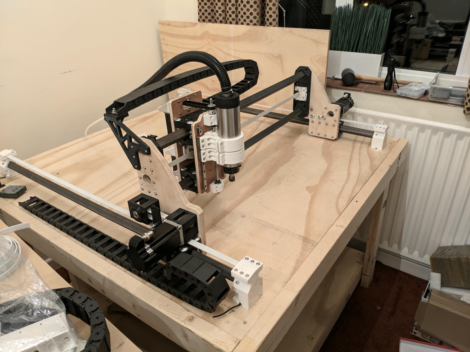
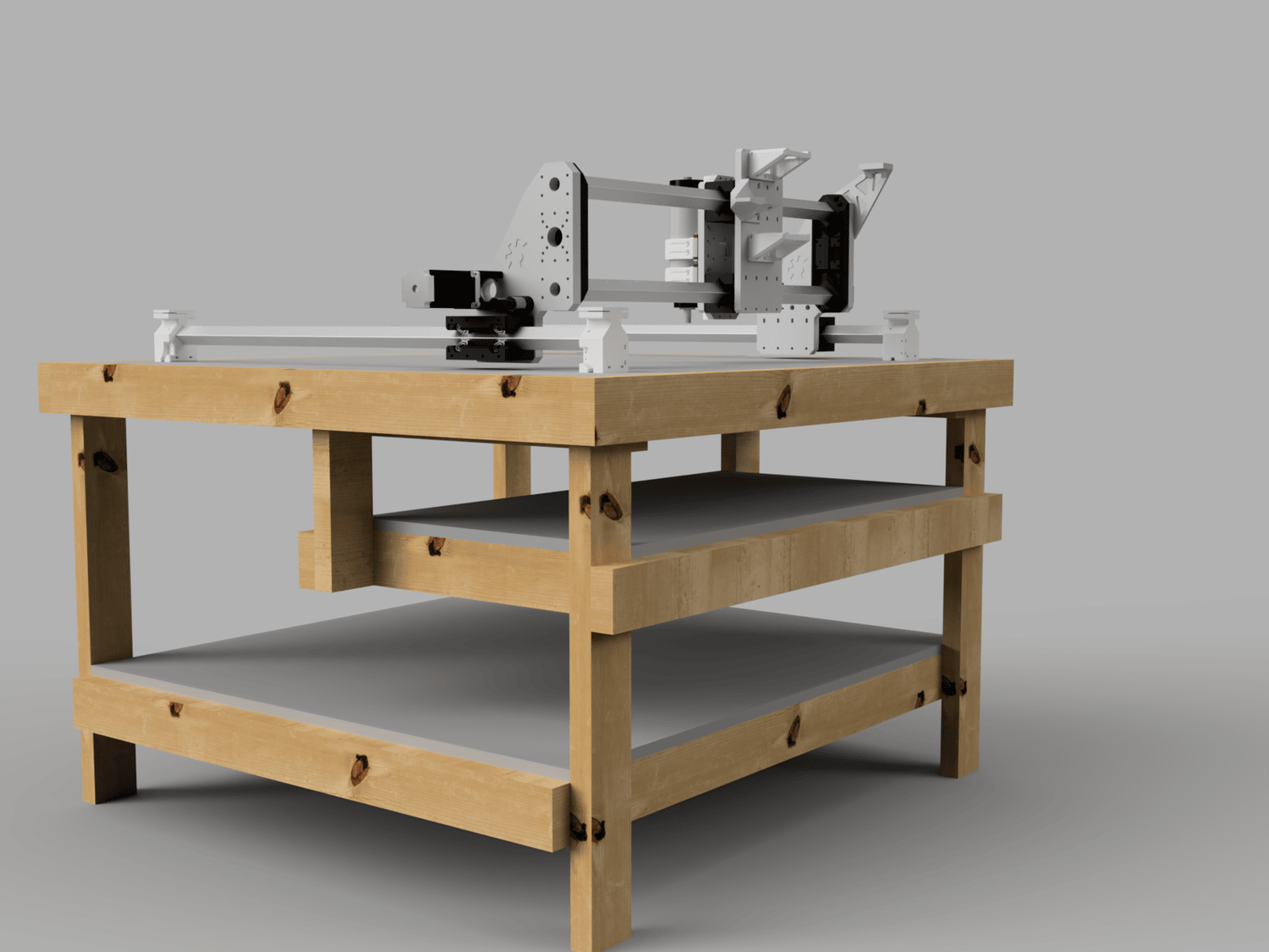
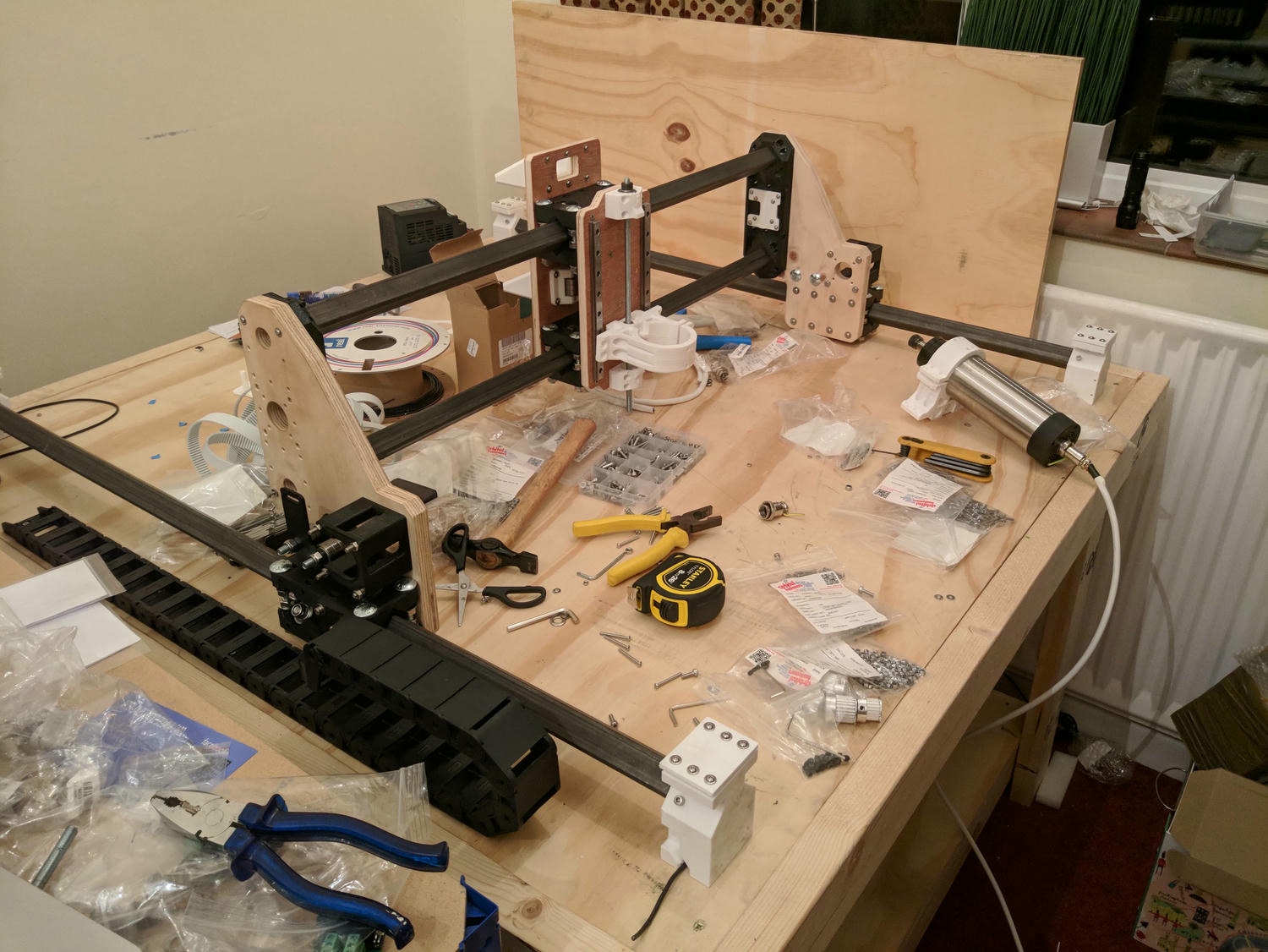
The design used is by Peter Newbery. It is constructed of mostly 3D printed parts with steel box section forming the rails. Belts drive the XY movement with a leadscrew for the Z axis. I considered other printable CNC options like the better known MPCNC, but appreciated the simplicity and openness of this design.
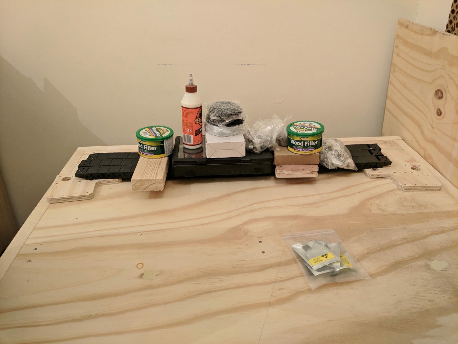
Frame
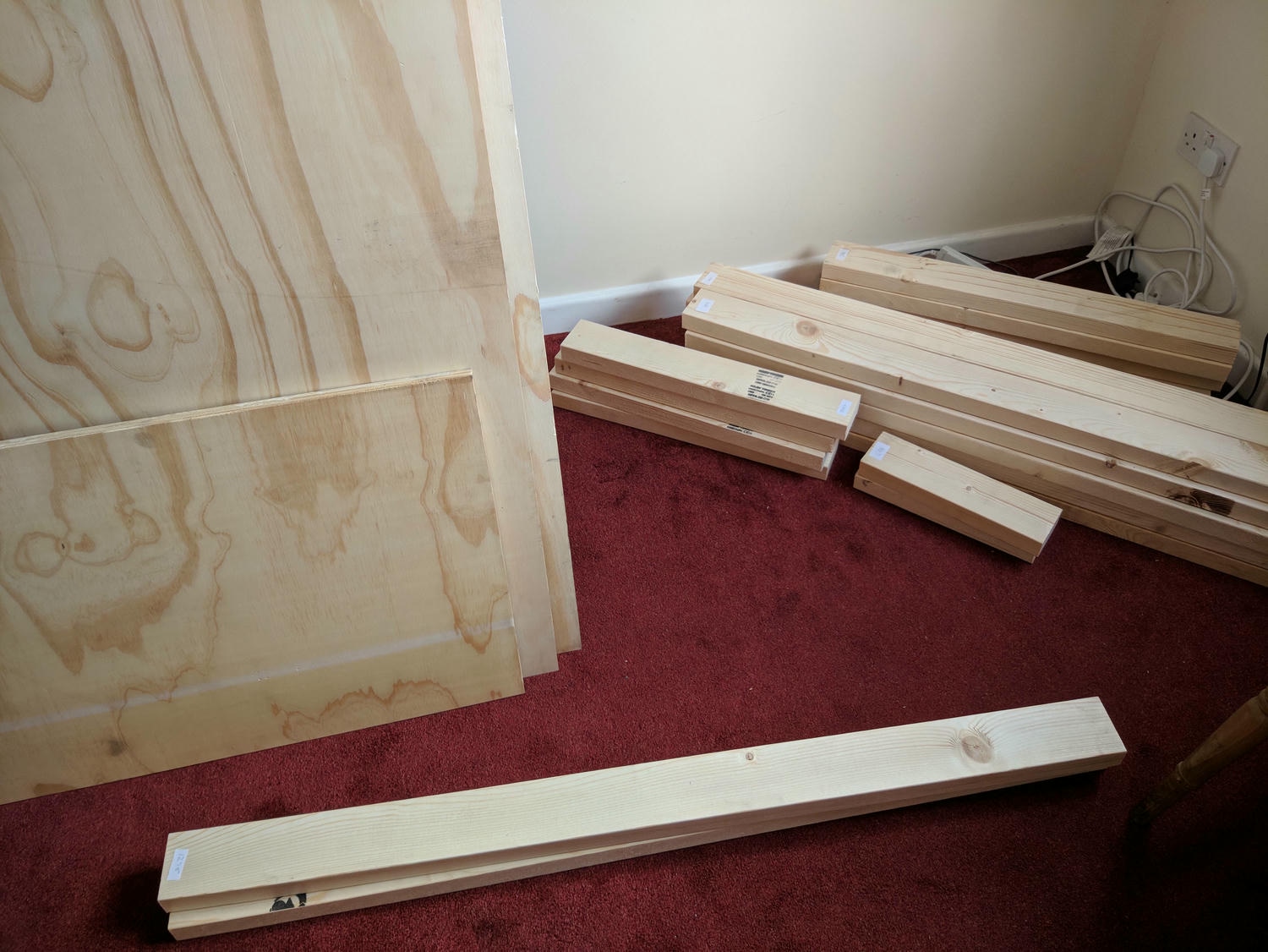
To start I needed a table to hold everything and got to work with my mitre saw – at this stage still in a carpeted spare bedroom.
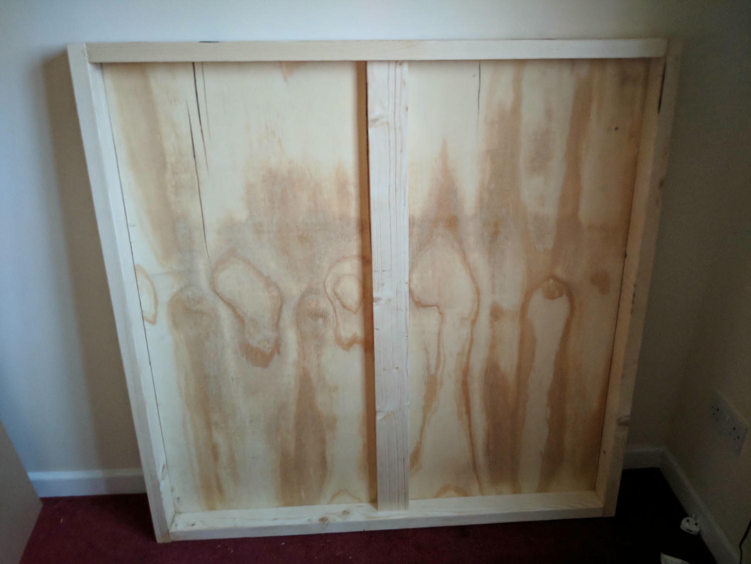
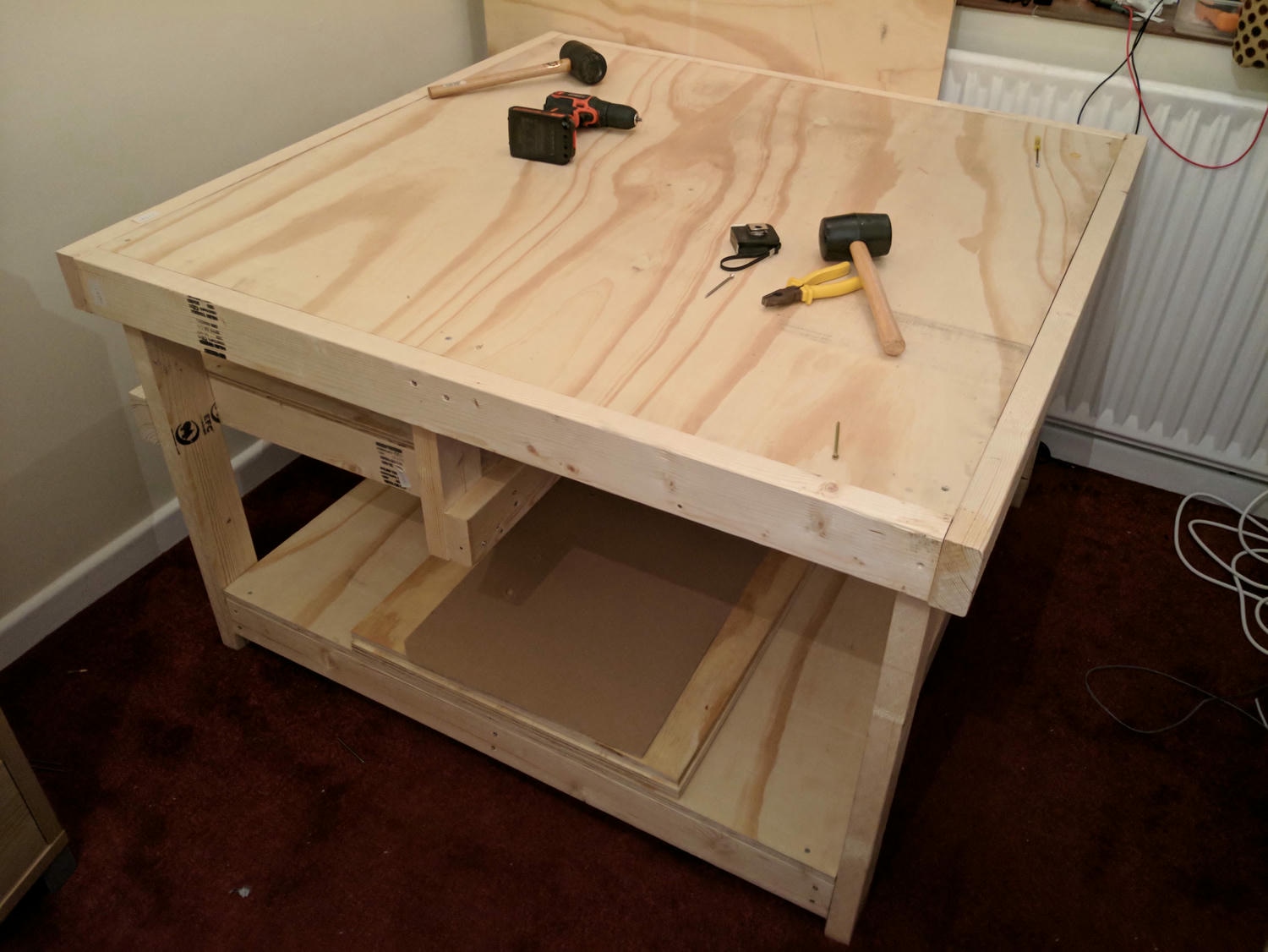
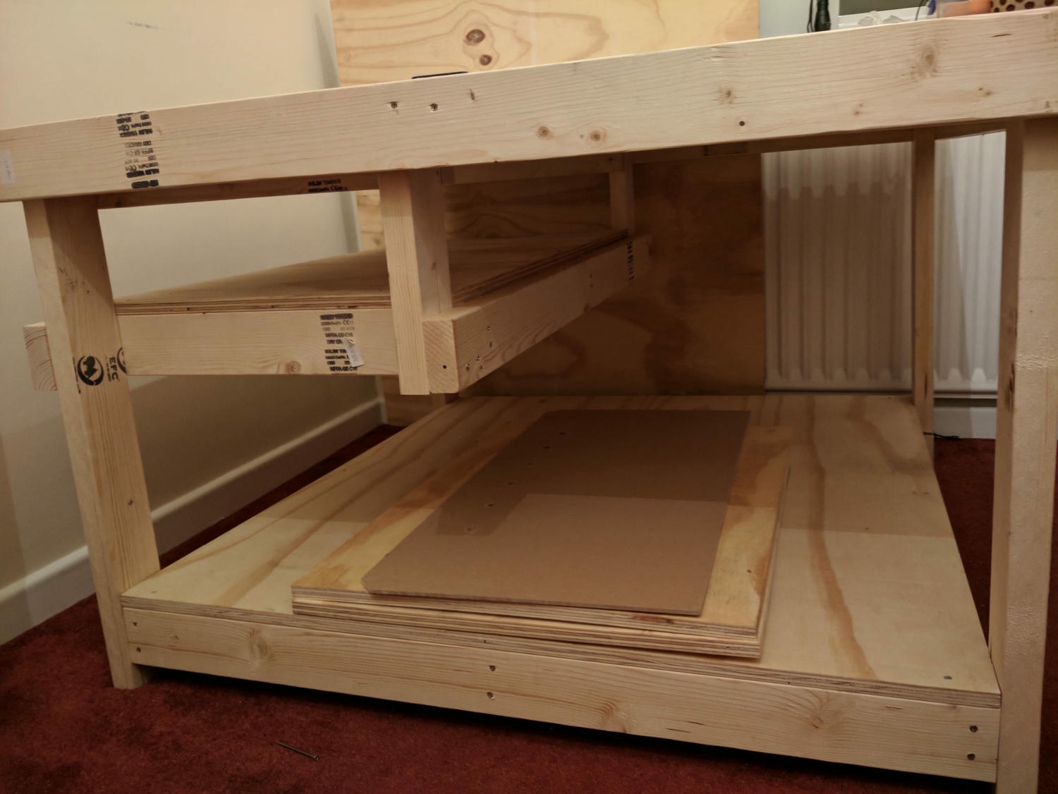
This frame was later modified to fold up onto the wall of my new workshop to save space.
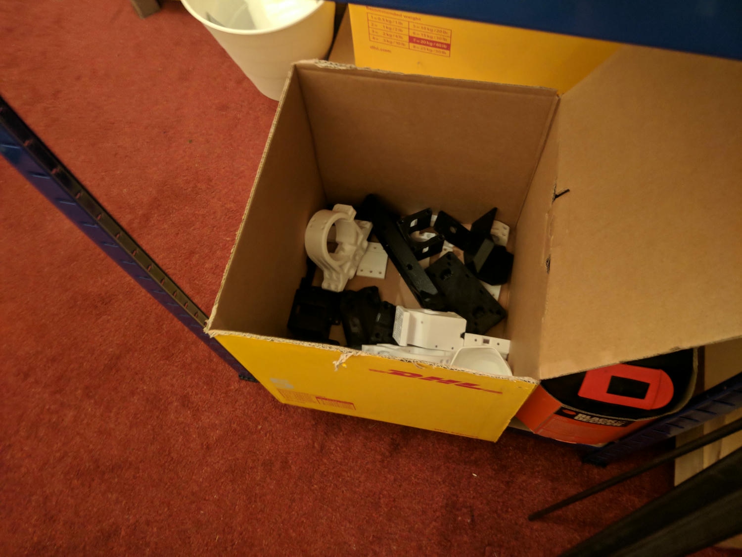
Components
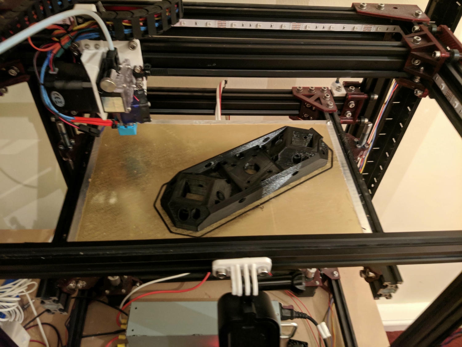
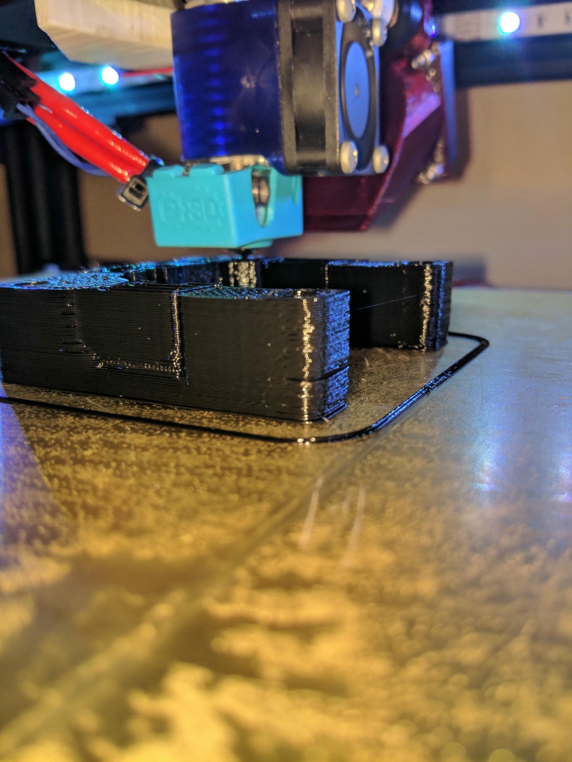
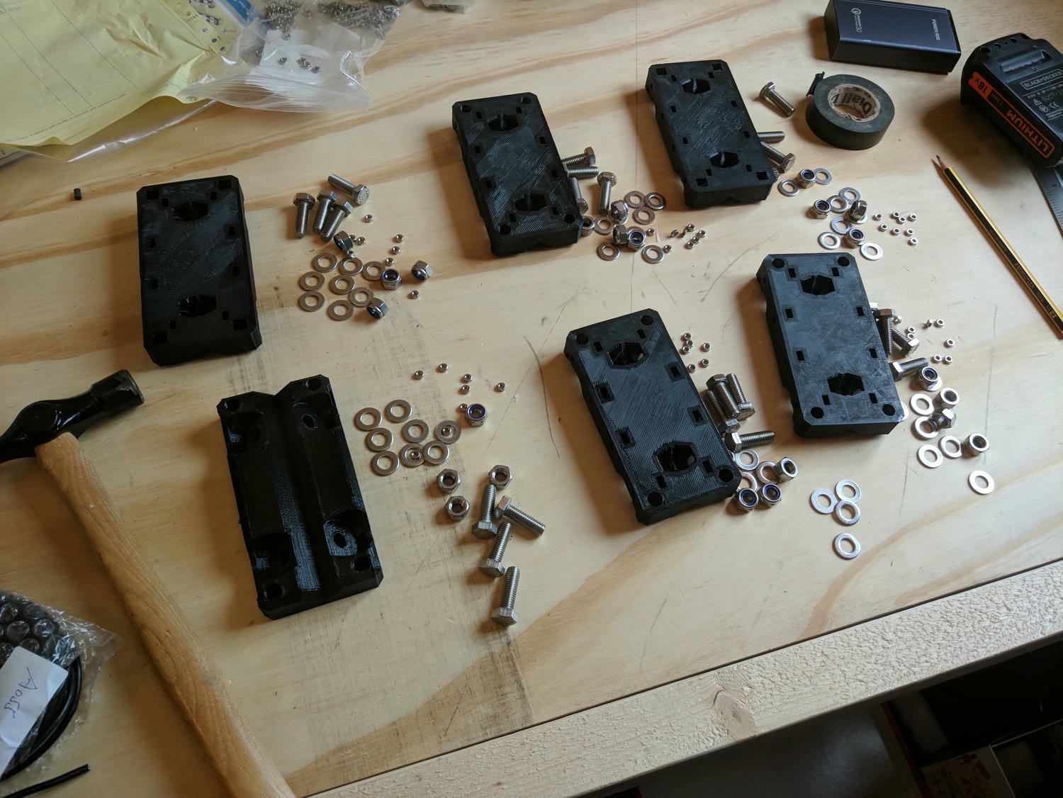
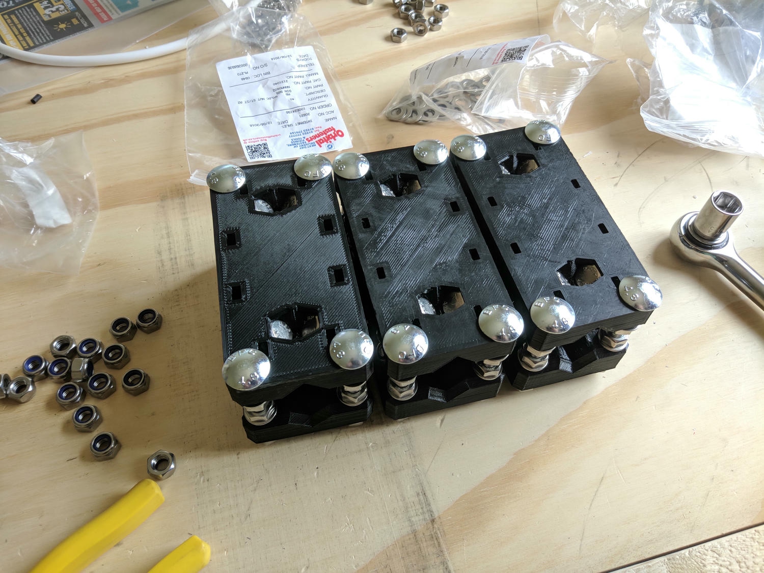
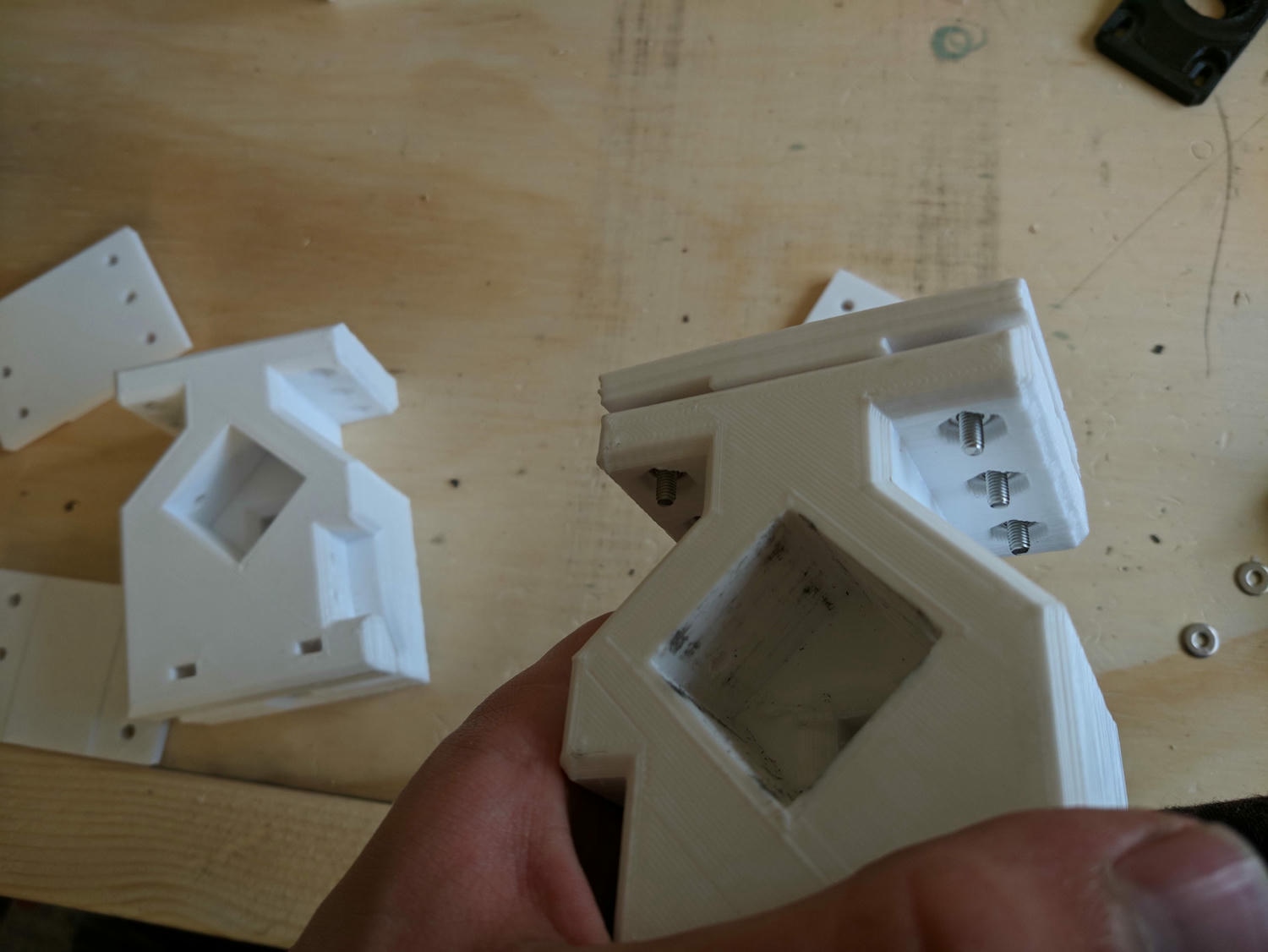
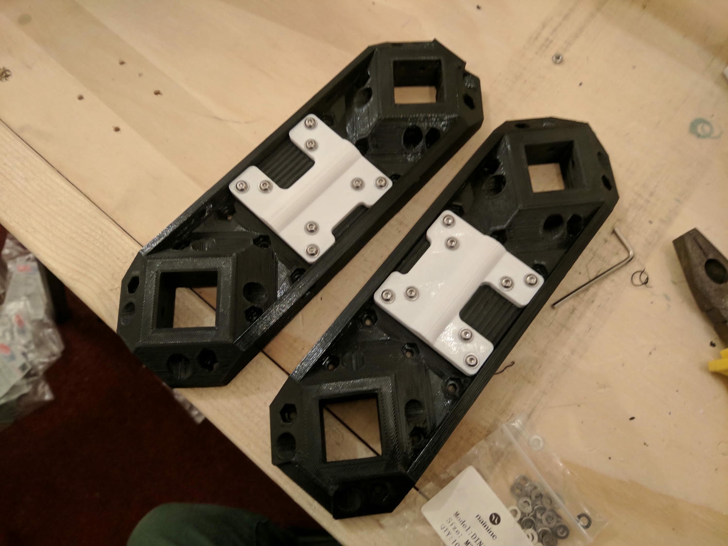
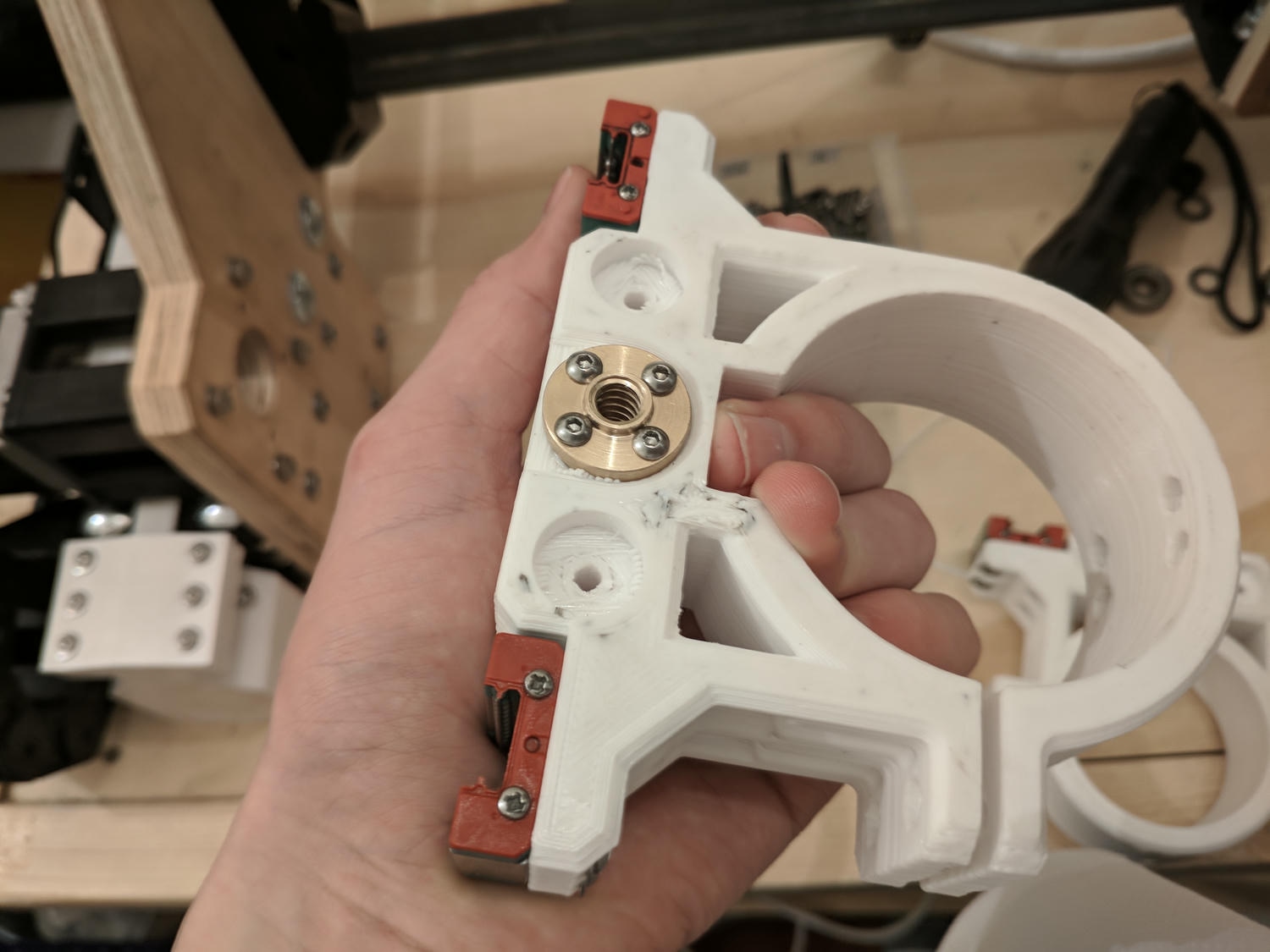
As this is a mostly printed design, the work started on my 3D printer with the parts produced in black and white PETG for strength. All of the motor mounts, axis constraints and carriage blocks are printed, with a few plywood parts completing the machine frame.
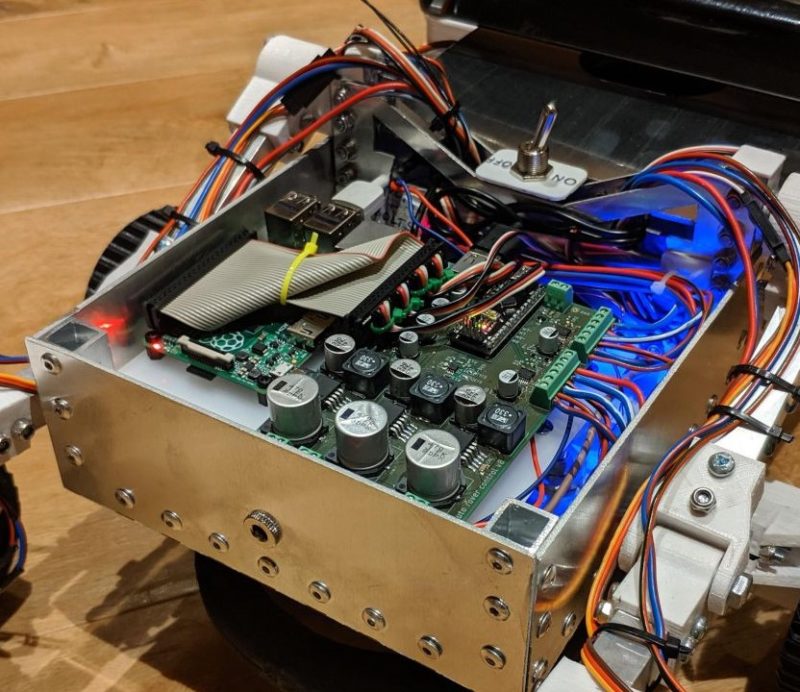
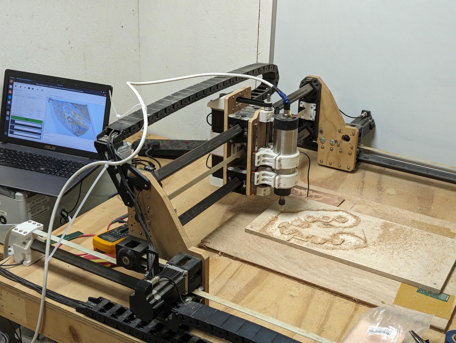
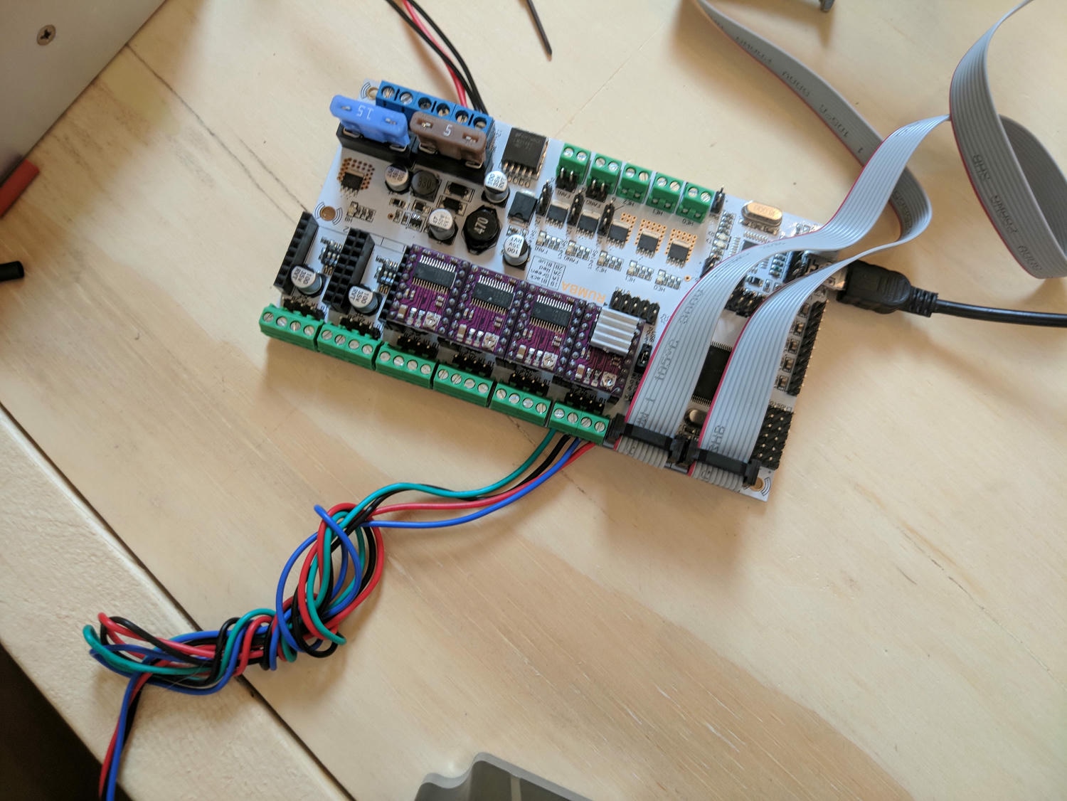
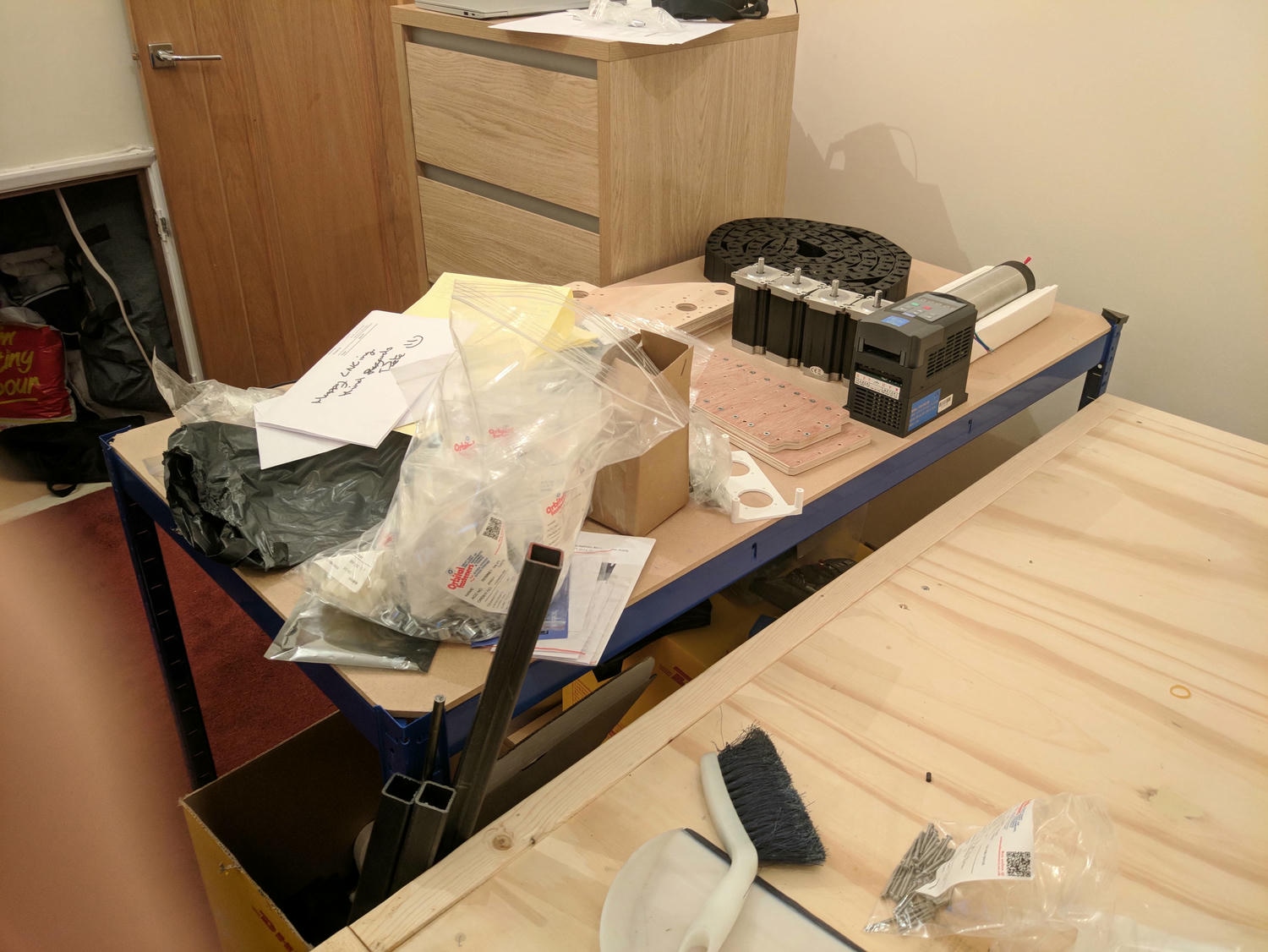
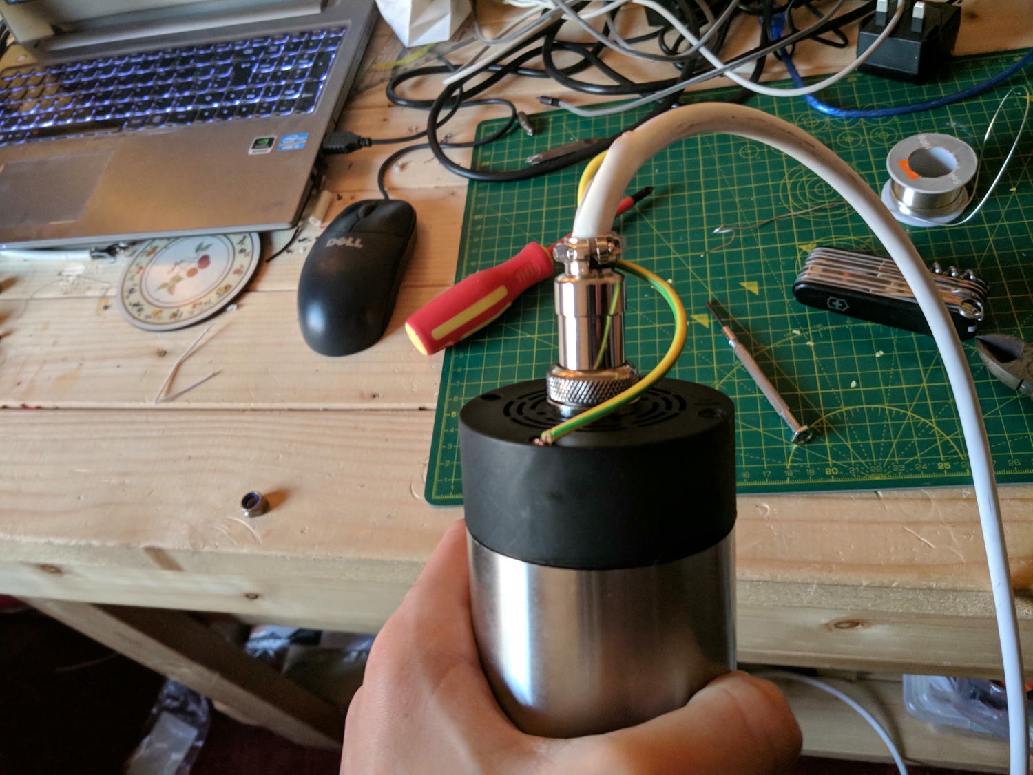
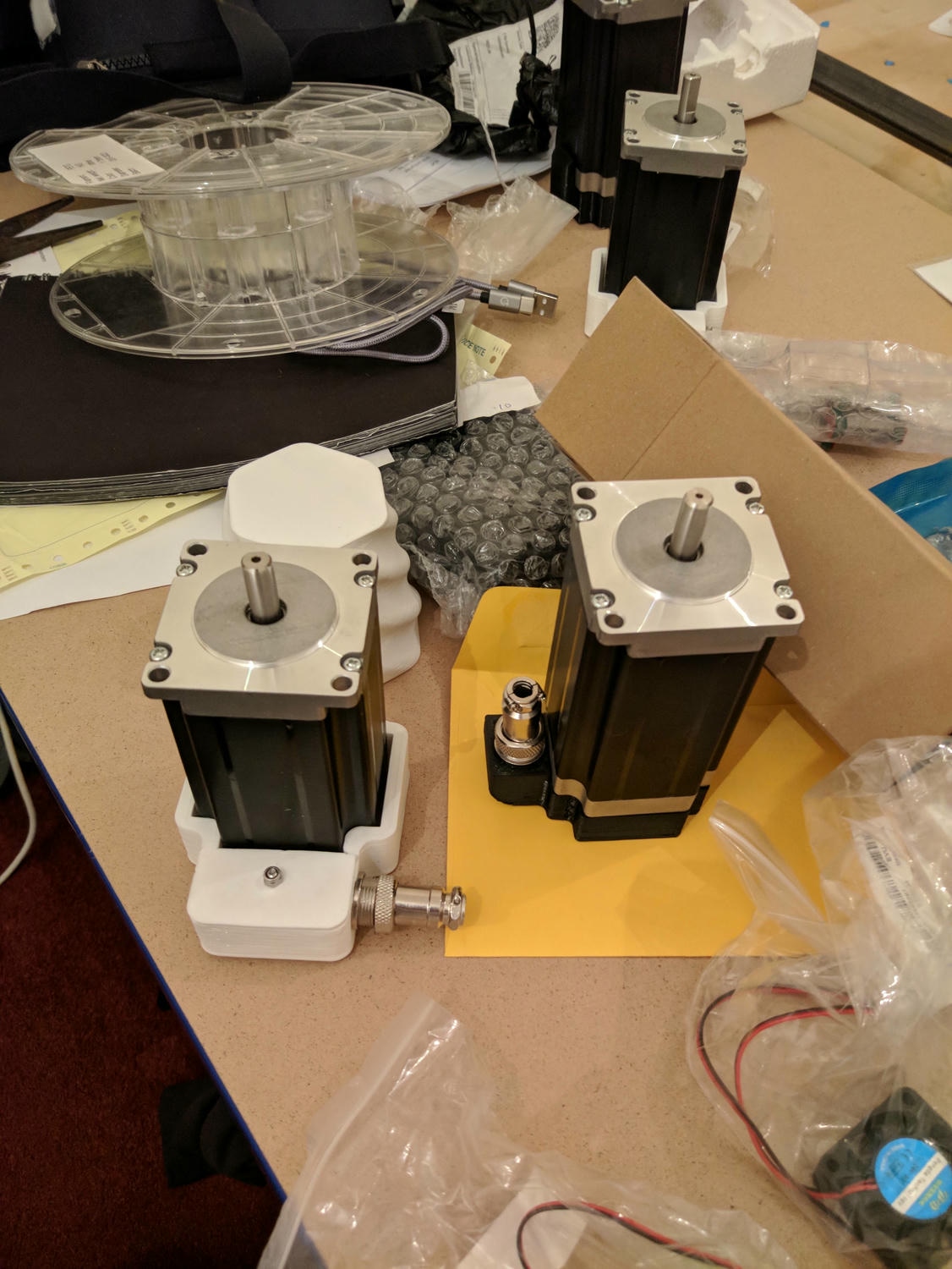
The key electronic components for movement are the control board, mounted stepper motor drivers and the stepper motors themselves – these allow extremely fine control of XYZ movement and distance measurement from a datum. For the cutter itself, I chose a 230V air cooled spindle driven by a VFD. The VFD (variable frequency drive) takes a mains single phase supply rail and converts it into a variable frequency three phase power line that is efficient, quiet and enables carefully controlled cutting speed.
Kinematics
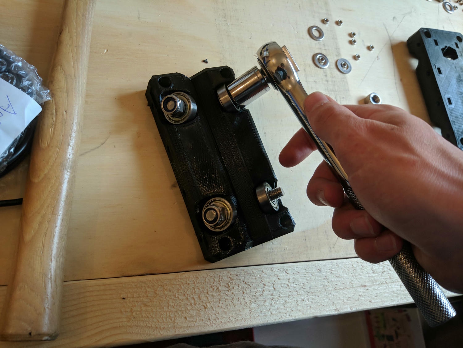
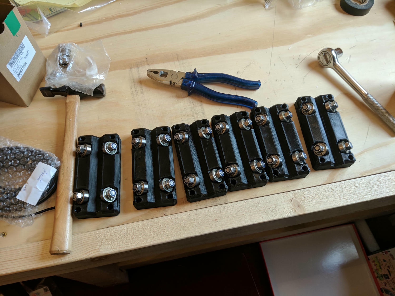
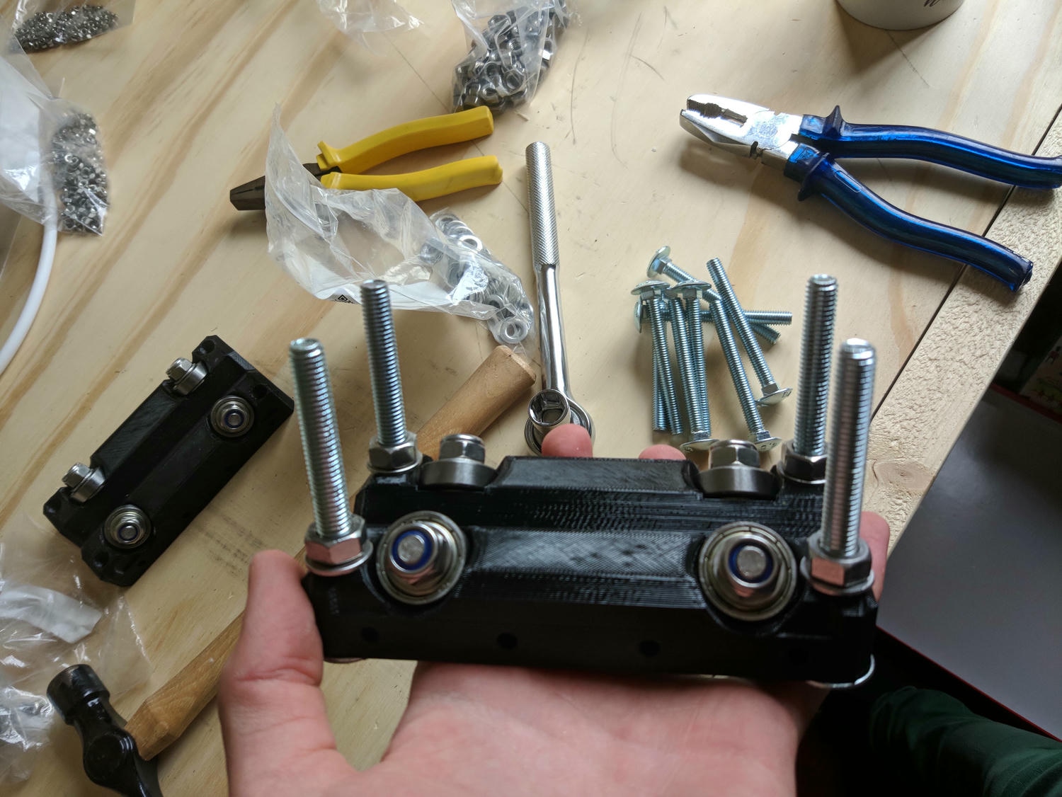
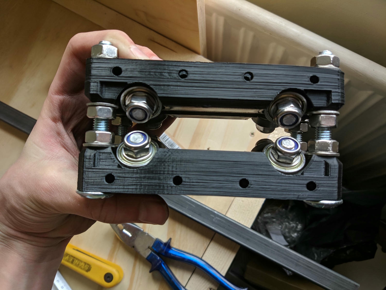
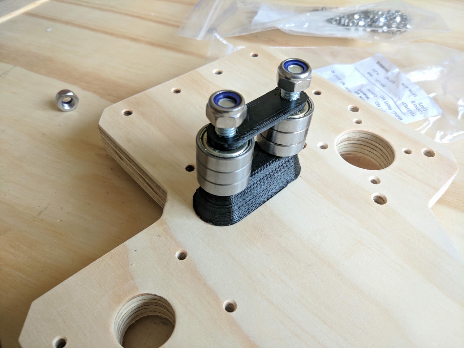
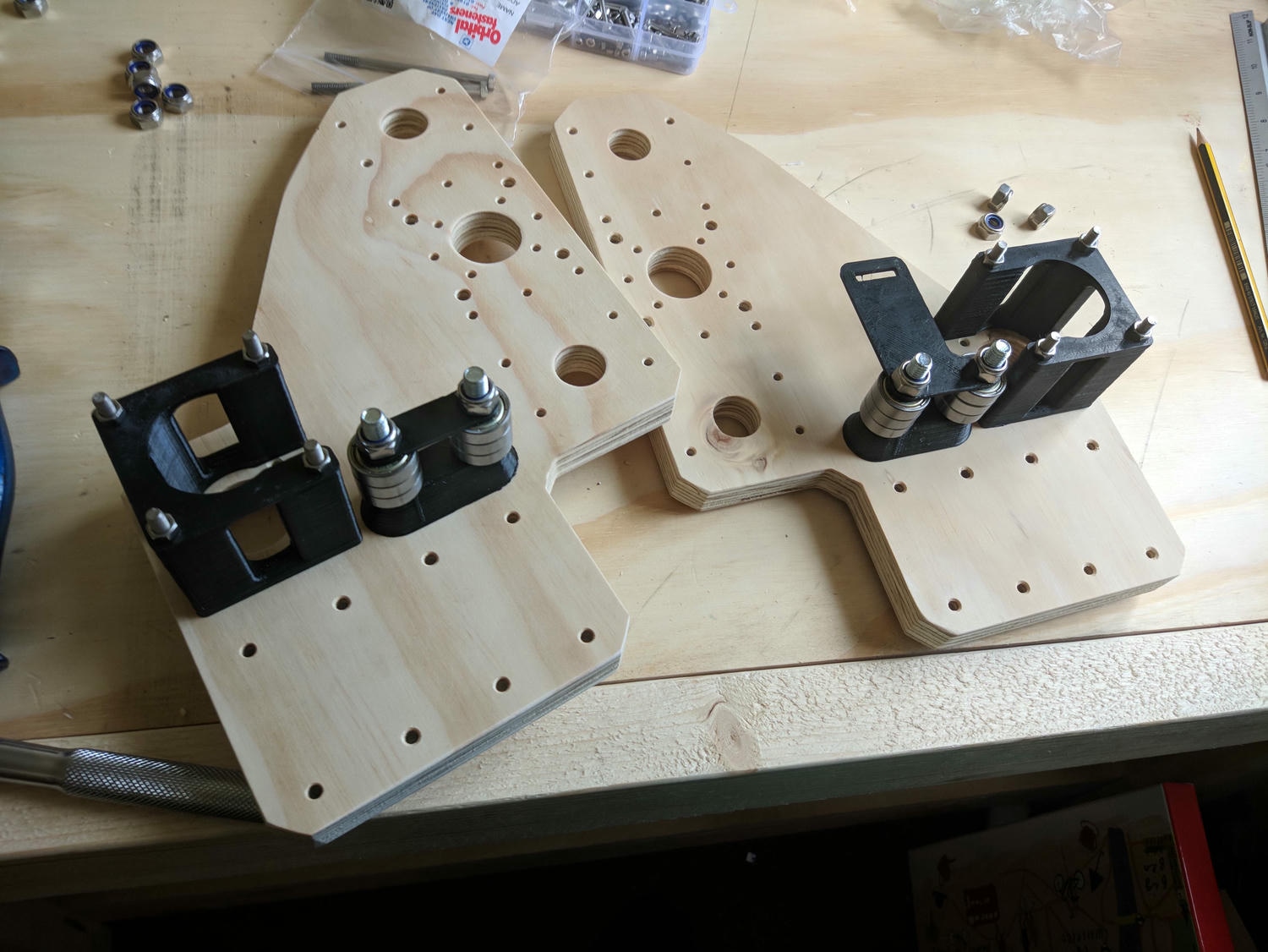
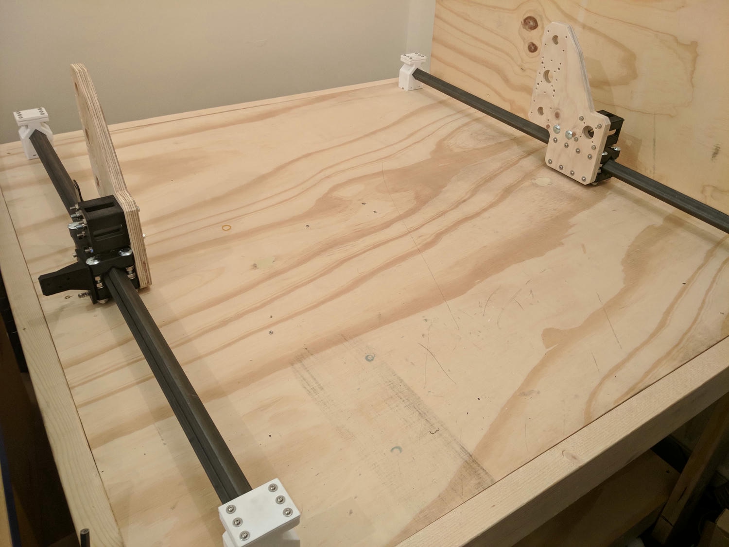
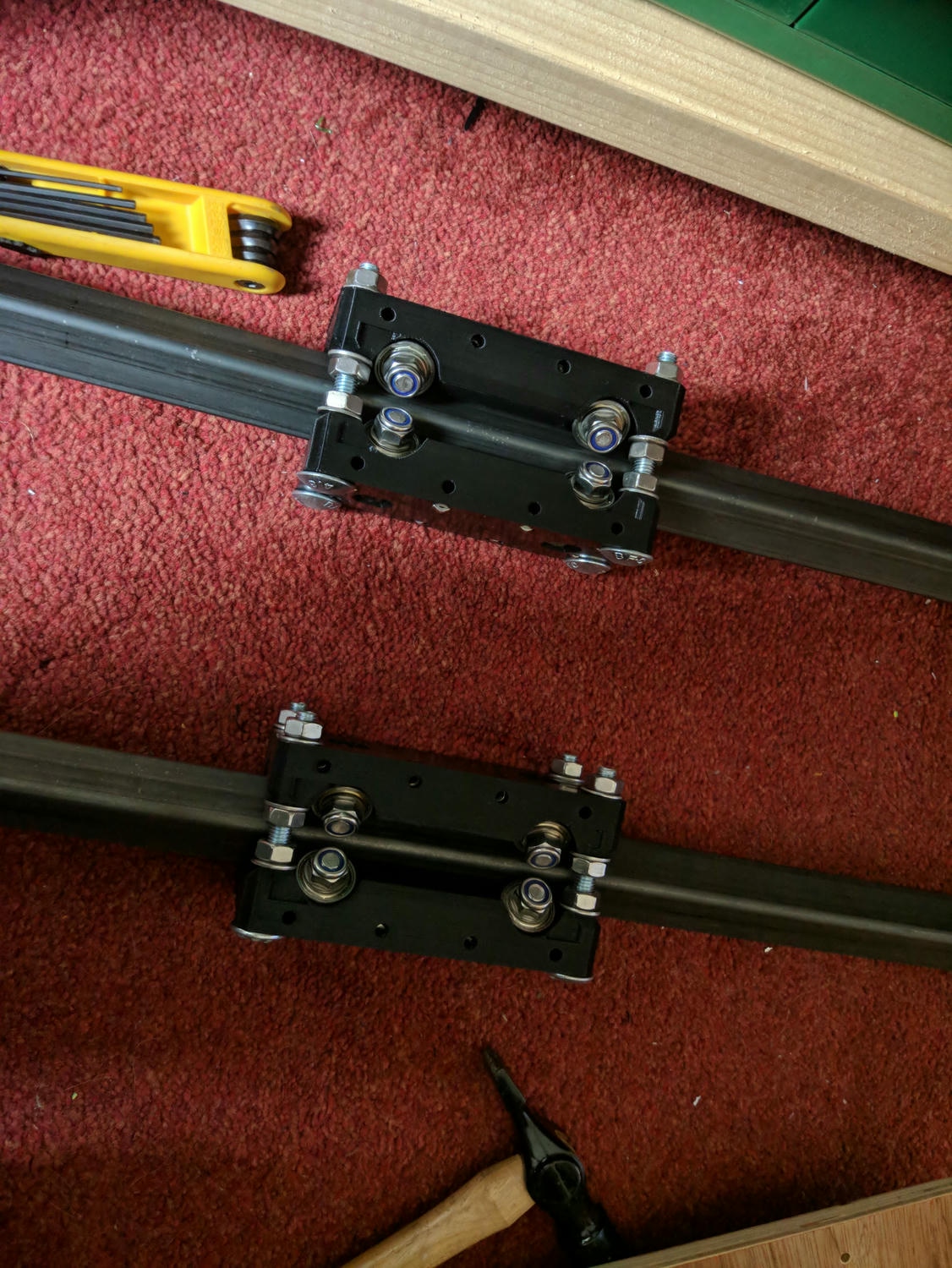
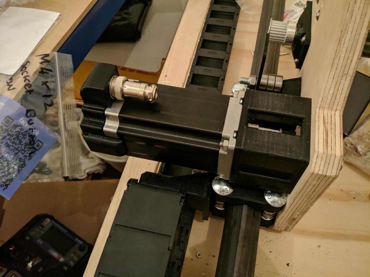
The kinematic design of the Root 3 is well thought through. Side (Y) carriages are assembled from the 3D printed blocks with integrated standard bearings and fixings to provide linear motion.
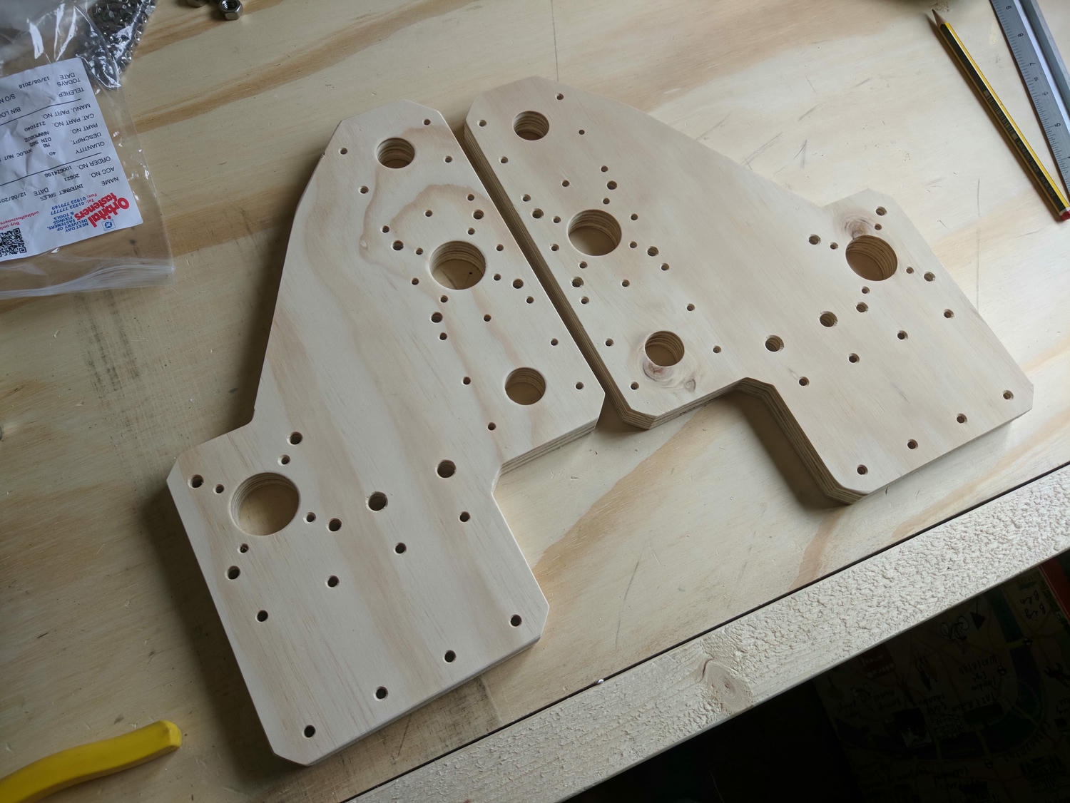
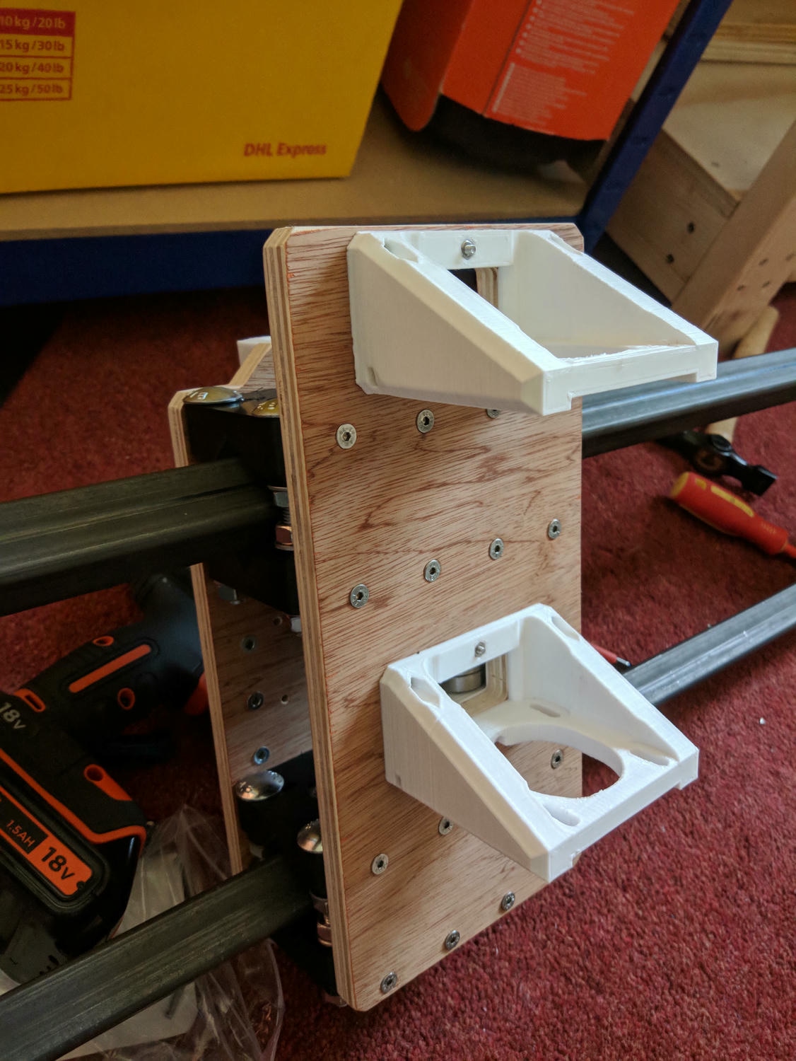
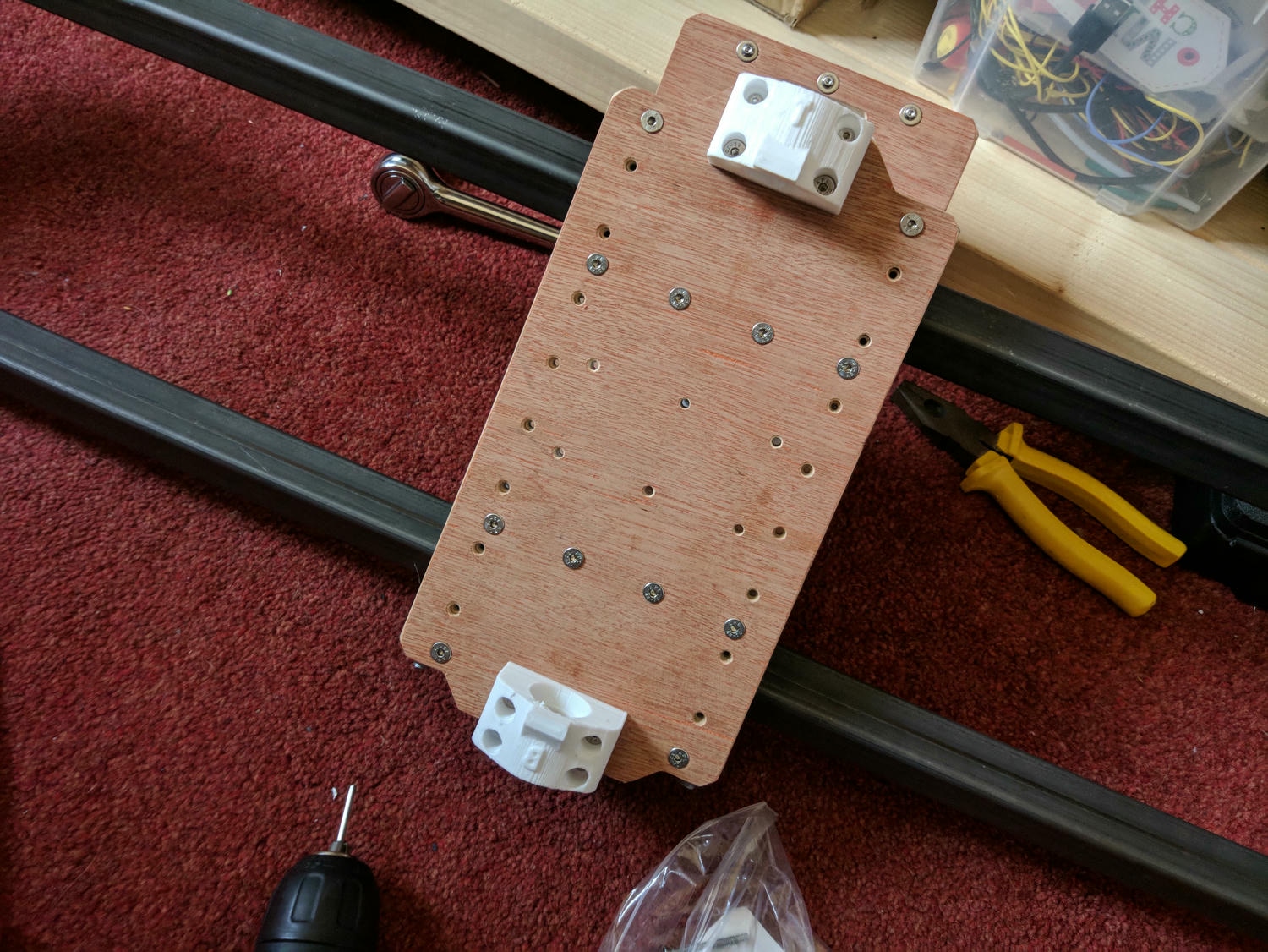
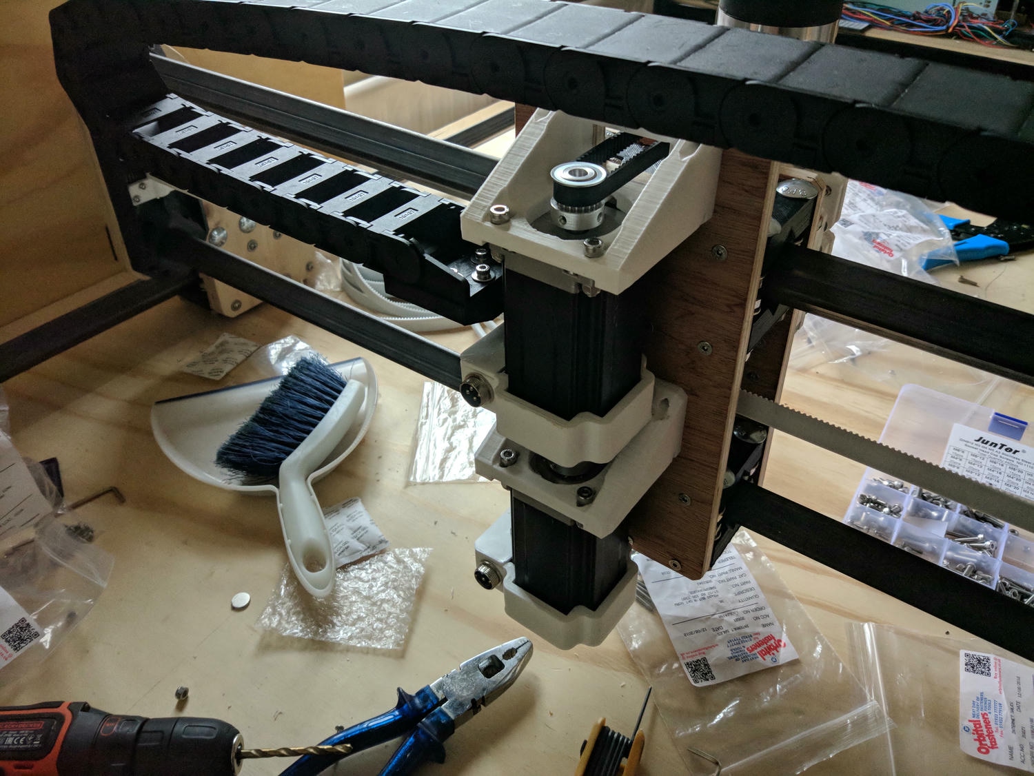
The carriages screw into router cut plywood side panels that I bought from Peter’s website. Belt idlers and motor mounts are also affixed here.
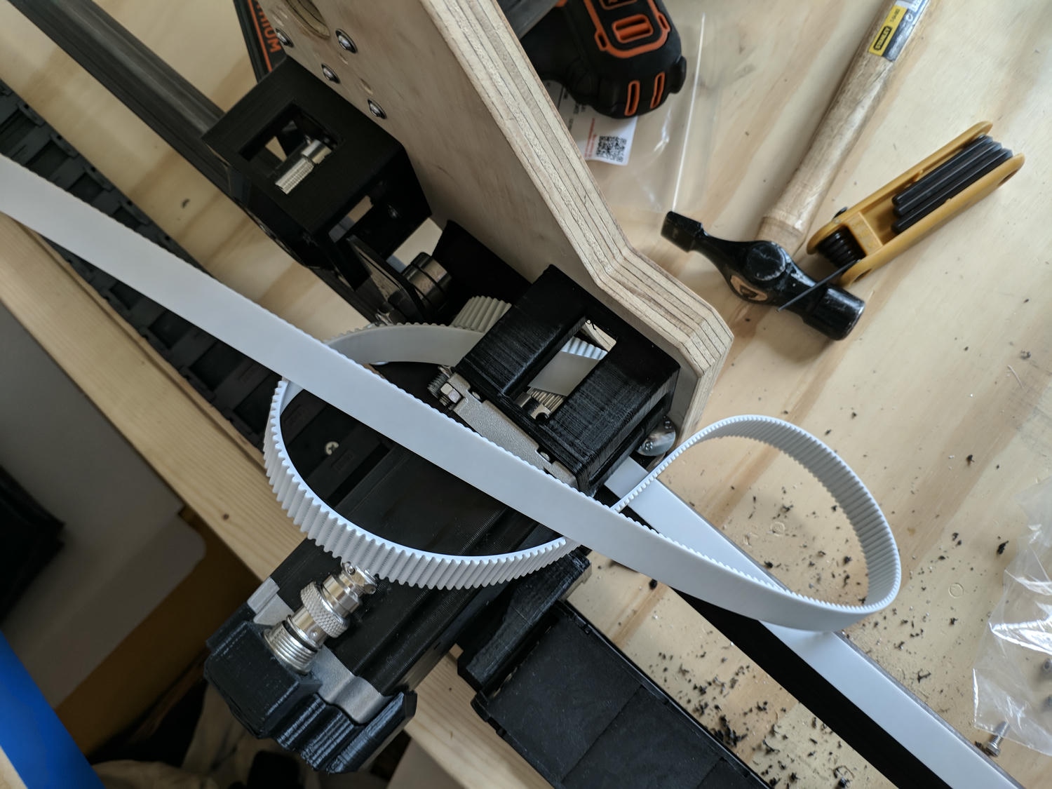
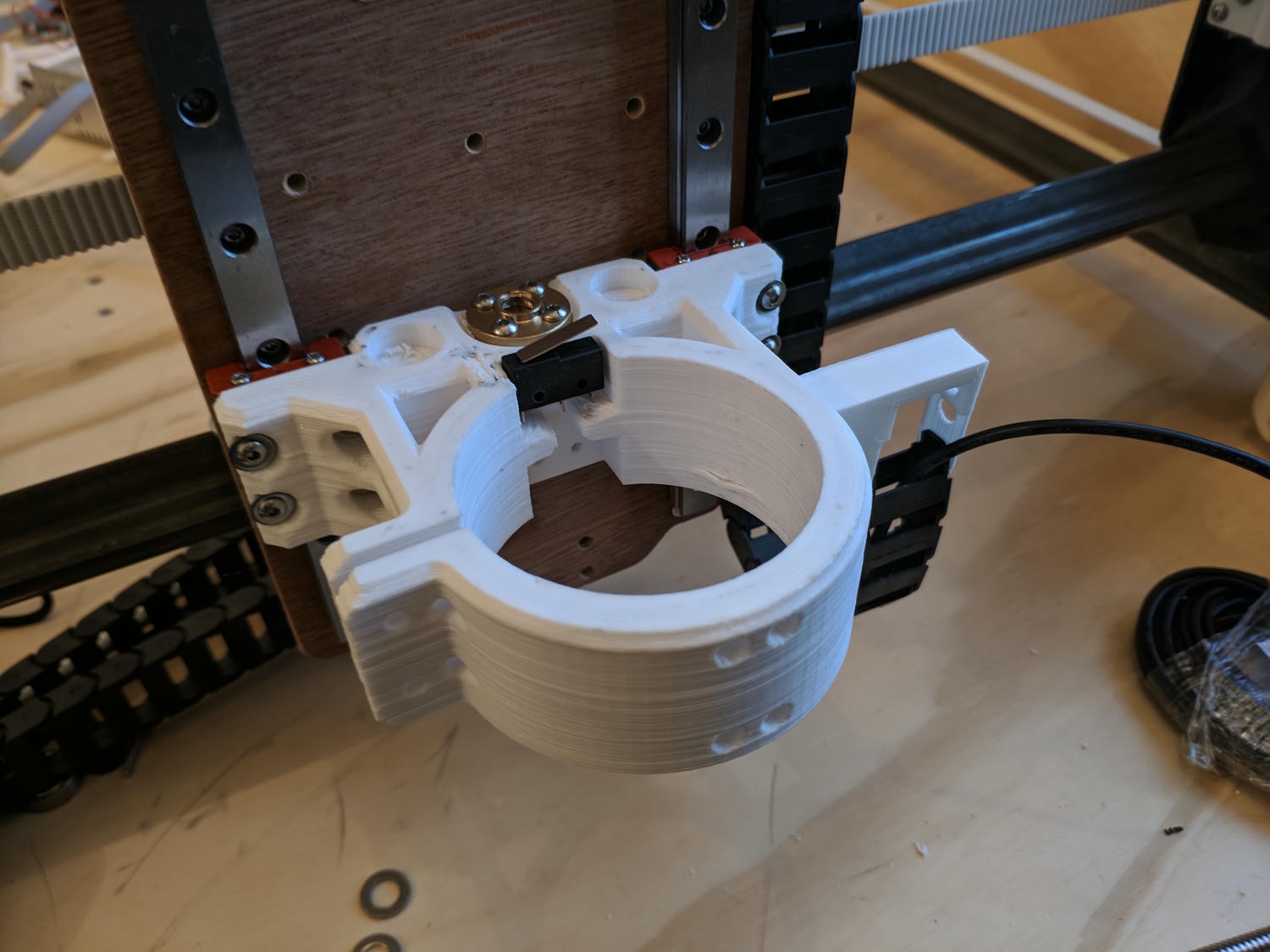
The metal gantry is held on the plywood base with four printed corners that the square tubes slide into; these corners also include belt clamps for tensioning.
With the Y axis complete I completed similar assembly steps for the XZ axes.
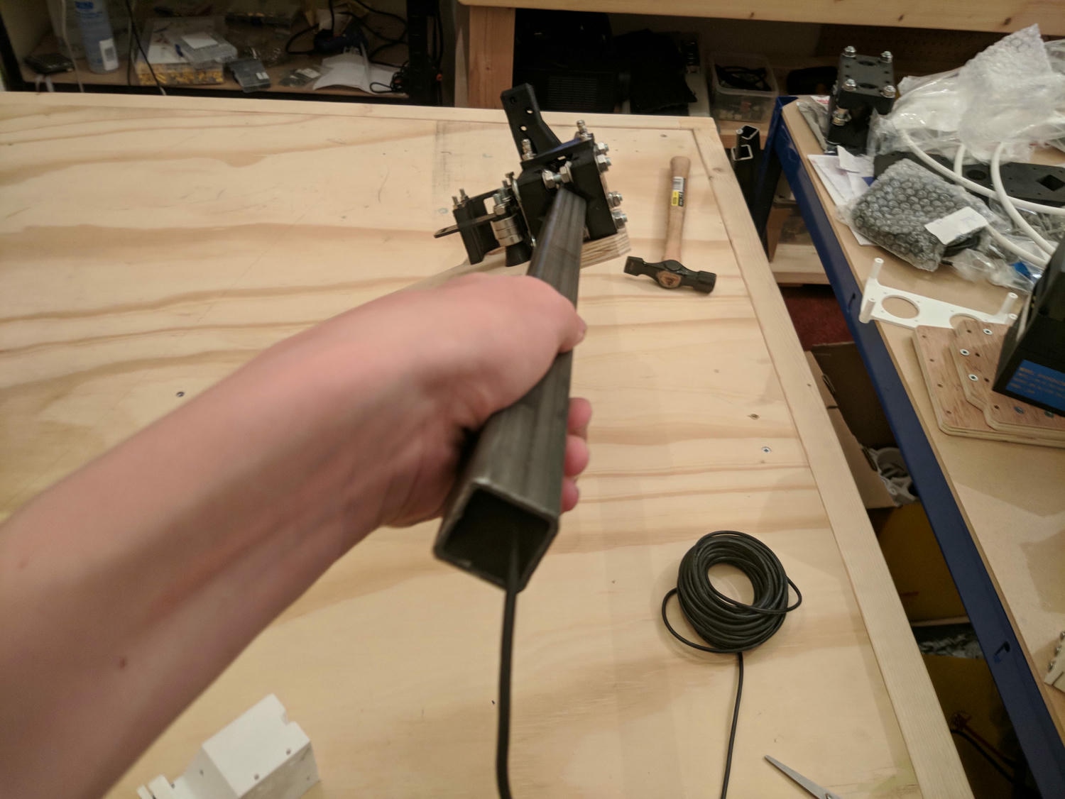
The XY motors on this machine are located on their respective axes and move with the cutting tool ‘self propelling’ the carriages into place. The Z axis is externally driven by a second stepper on the moving gantry and a leadscrew.
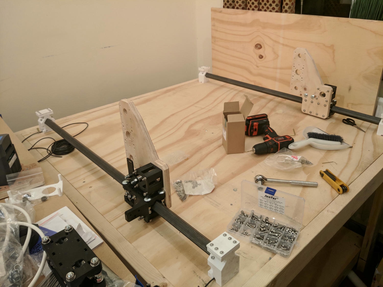
The assembly might look complicated but good documentation meant it was very much a case of instruction following.
Once everything was fixed, I could guide the belts through the idlers and tension them.
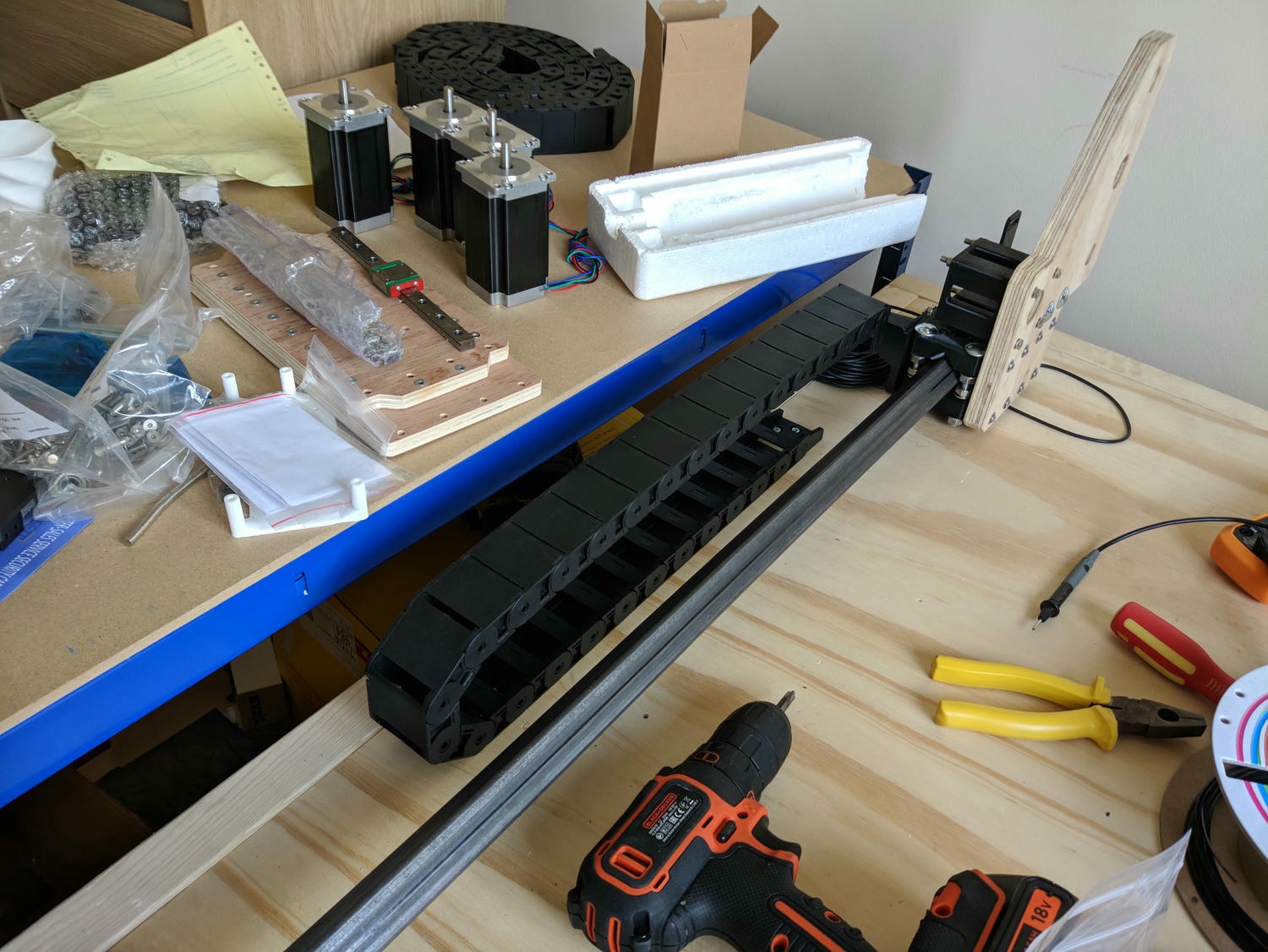
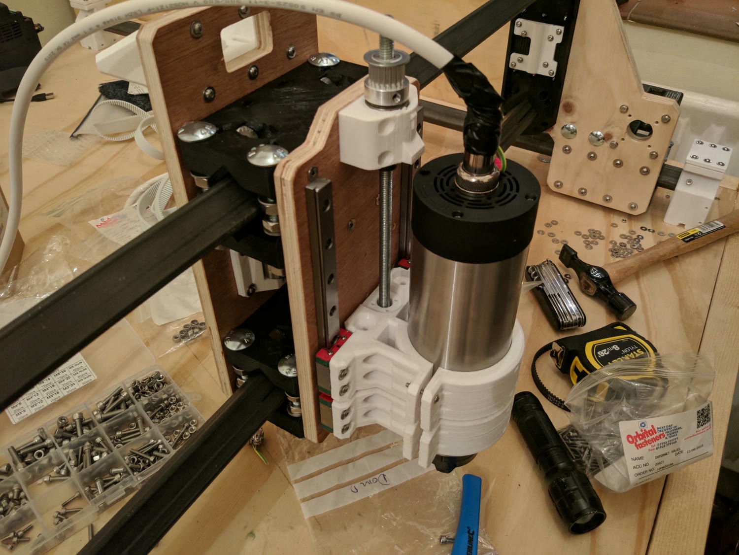
Cable routing and wiring
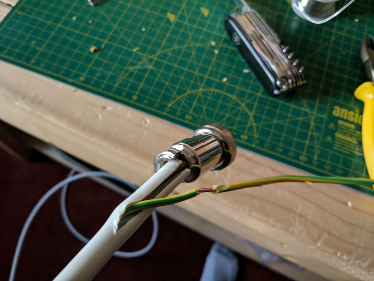
Cable chains guide the drive and endstop wiring as the machine moves. The spindle is driven by a 3ph VFD; classically, the casing wasn’t earthed so I had to do this manually with a crimp attached to a housing screw.
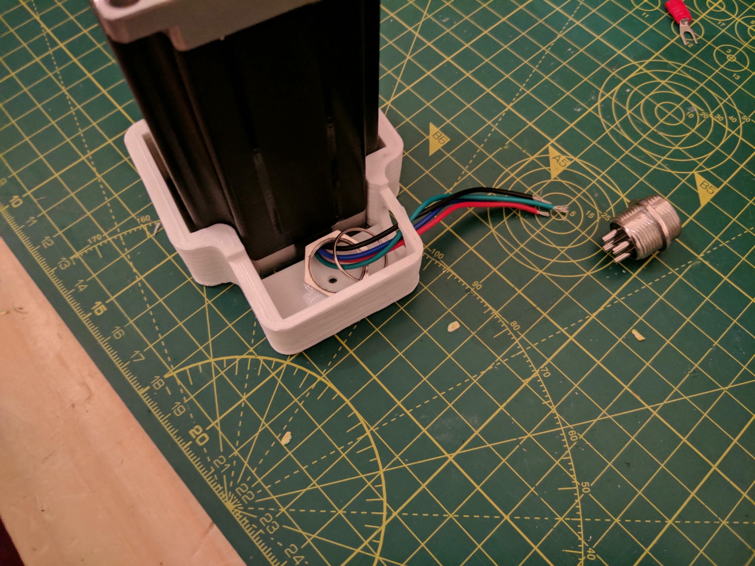
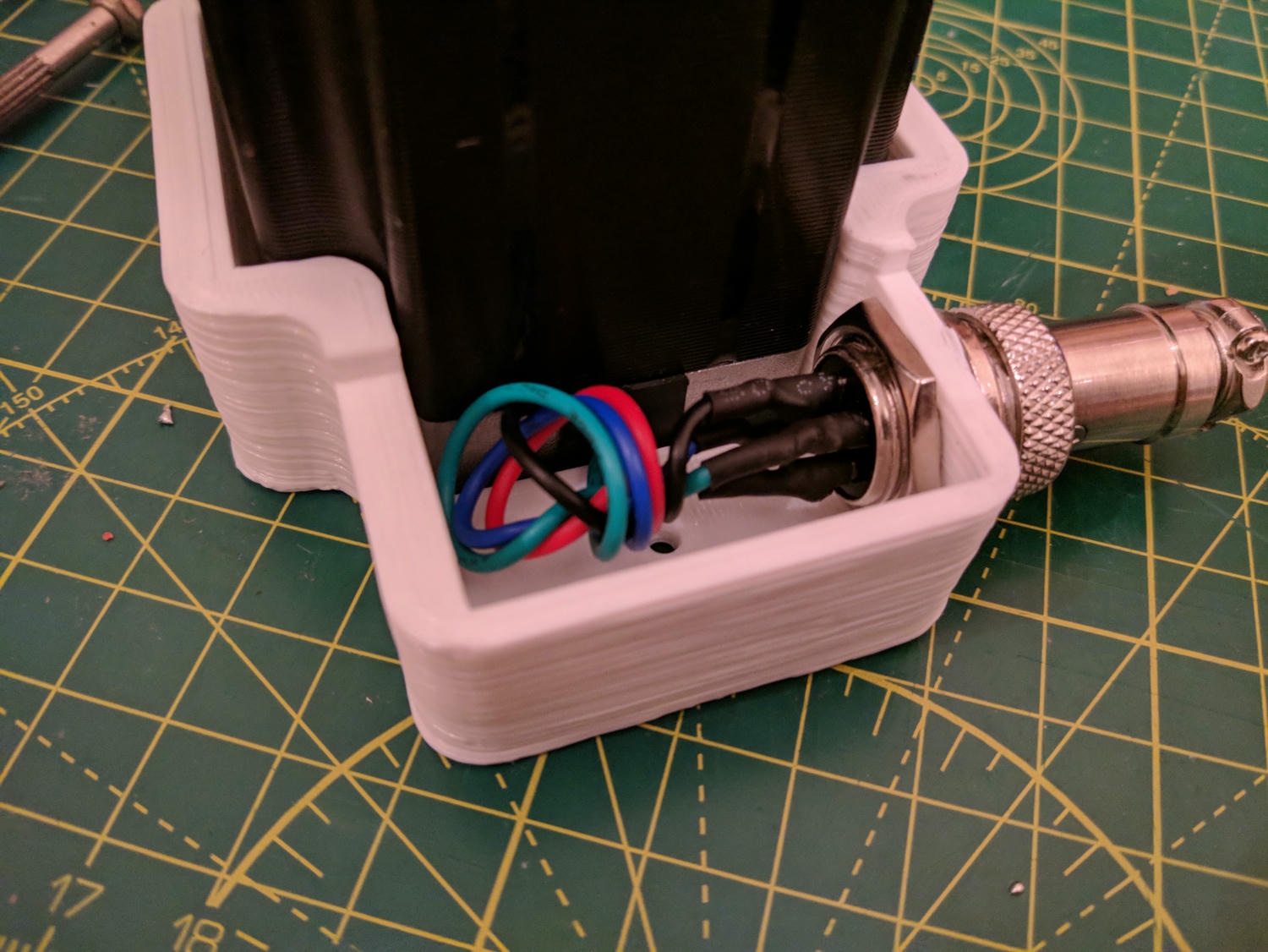
When wiring the motors, I decided to introduce a connector at the termination point – this was a decision I later regretted as it led to difficulty fitting everything together.
With that the frame and kinematics were complete! This is the work I finished a long long time ago (hence the brevity of the captions). The only problem was the lack of drive electronics with an ETA of 5 years later. See the next post for further details.