It wasn’t until the third year of my engineering degree that I was set off on a major design project, but after eight gruelling terms of linear algebra and laboratory experiments, it was welcome relief. The scope of the brief was wide – ‘manufacturing a better world’ – and the idea was to see if we were able to apply some of our theoretical knowledge on a real engineering problem. This was also a group project, which meant the further challenge (and fun) of teamwork, far outside the comfort zone of a cohort of under-socialised STEM students.
Since our official presentations and submissions communicate the idea and mission behind the project, I’m going to use this post to focus (more graphically than textually) on technical design elements which might otherwise be forgotten.
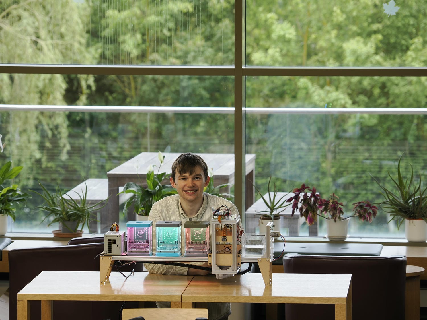
I’m grateful to Scarlett, Aisling and Yiheng for being such great team members; the work featured below is the fruit of our collective effort.
The Idea
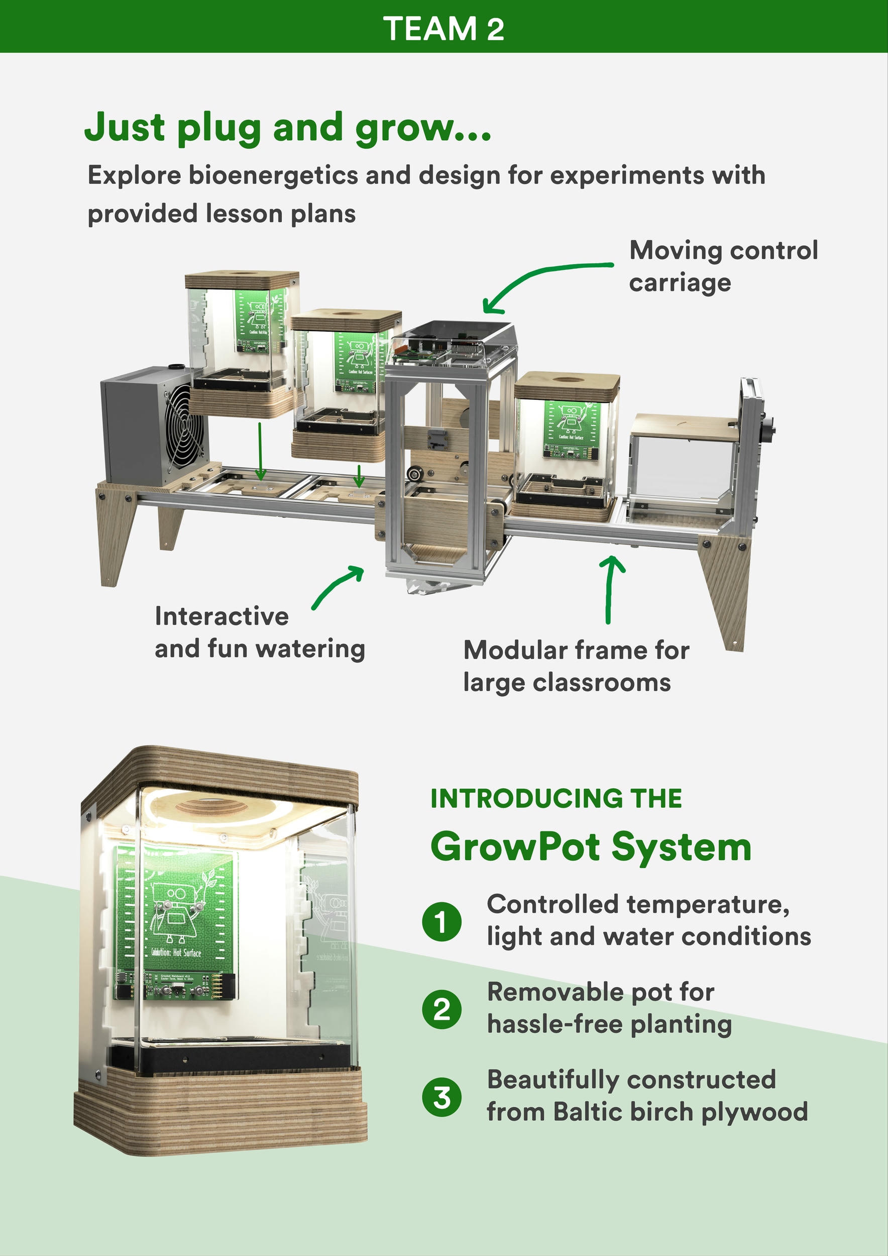
On the basis of the broad initial brief, our group got brainstorming about how we could best approach the task. Inspired by existing projects like FarmBot and NASA’s Plant Growth Habitat, we were drawn to agri-robotics, recognising potential for new applications in education. Lab grade plant growing chambers are commercially available, but can cost thousands of pounds and are not geared for school and undergraduate environments. Our aim was to create an affordable alternative with similar functionality: the ability to control temperature, humidity, watering cycles and lighting of multiple plants as they grow. Alongside this we envisaged a platform which would enable students to explore plant science and experimental design as part of interactive classroom sessions.
Take one example application in a 6th form biology curriculum: a class of 25 students could be split into 5 small groups, and each designated a Growbot module to work with. By considering parameter orthogonality, the class could together investigate into how different habitat variables impact growth of a particular plant. This style of learning has the potential to be far more self-directed and memorable than a traditional lab.
Module design
Modularity was an early design priority, to ensure flexibility and scalability. While we originally considered designs with large singular growing beds, we realised that temperature and light control would be easier in discrete containers. This choice had the added benefit of segmenting the product into multiple interfacing parts which could be designed separately. Some functions couldn’t viably be included in every module, so the complicated watering system and expensive camera were situated on a moving carriage that could access the stationary modules as needed.
Each module needed to be durable, portable and hot-swappable. Beginning with initial sketches, we focused on form and construction; Fusion 360 was used for all CAD once high level principles had been established. We knew we would have to make the product with a tight turnaround, so a cautious design strategy was adopted: all components had to perform an uncomplicated and necessary function.
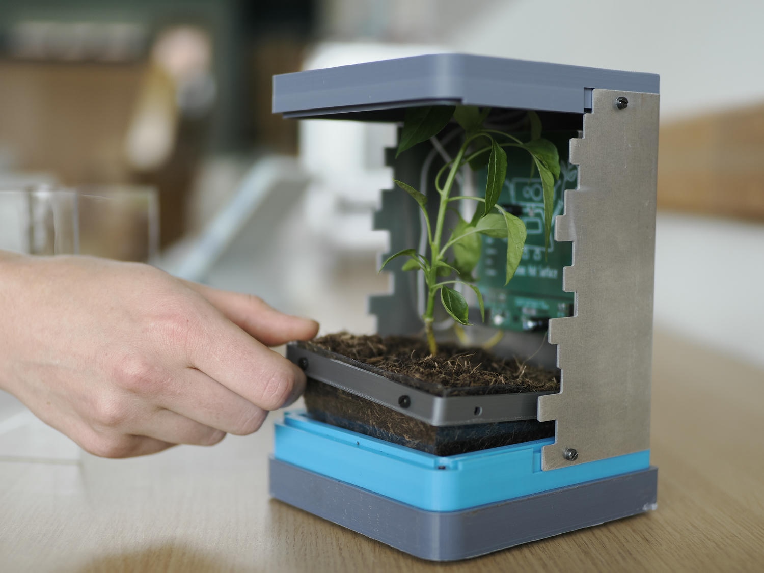
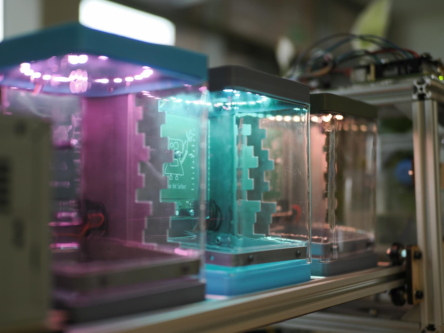
Being able to see the plant during growth is important, so all of our ideas included transparent windows. Making the pot removable and drainable was a further challenge. We decided three pods would be enough for our prototype model.
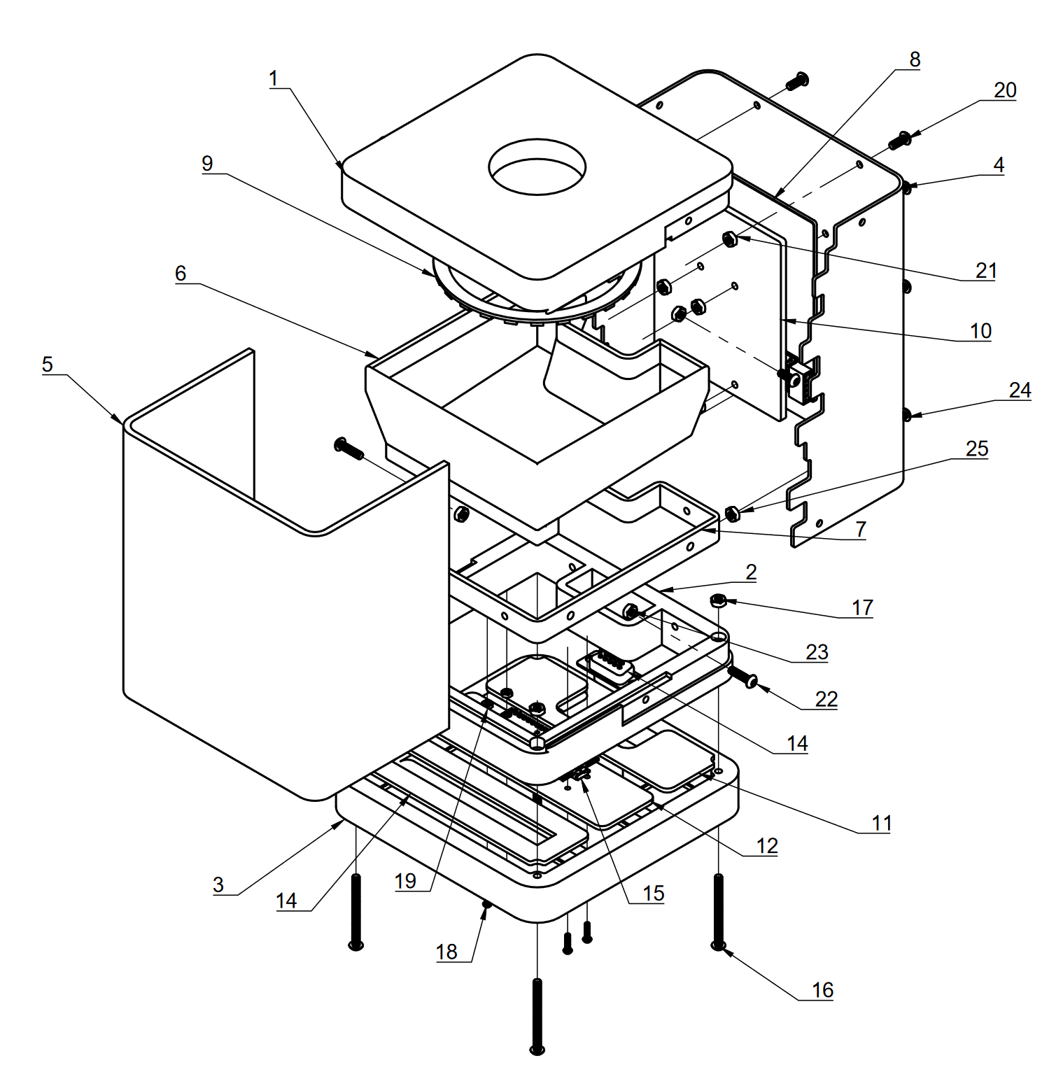
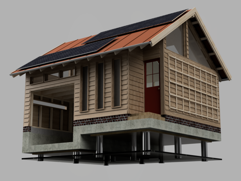
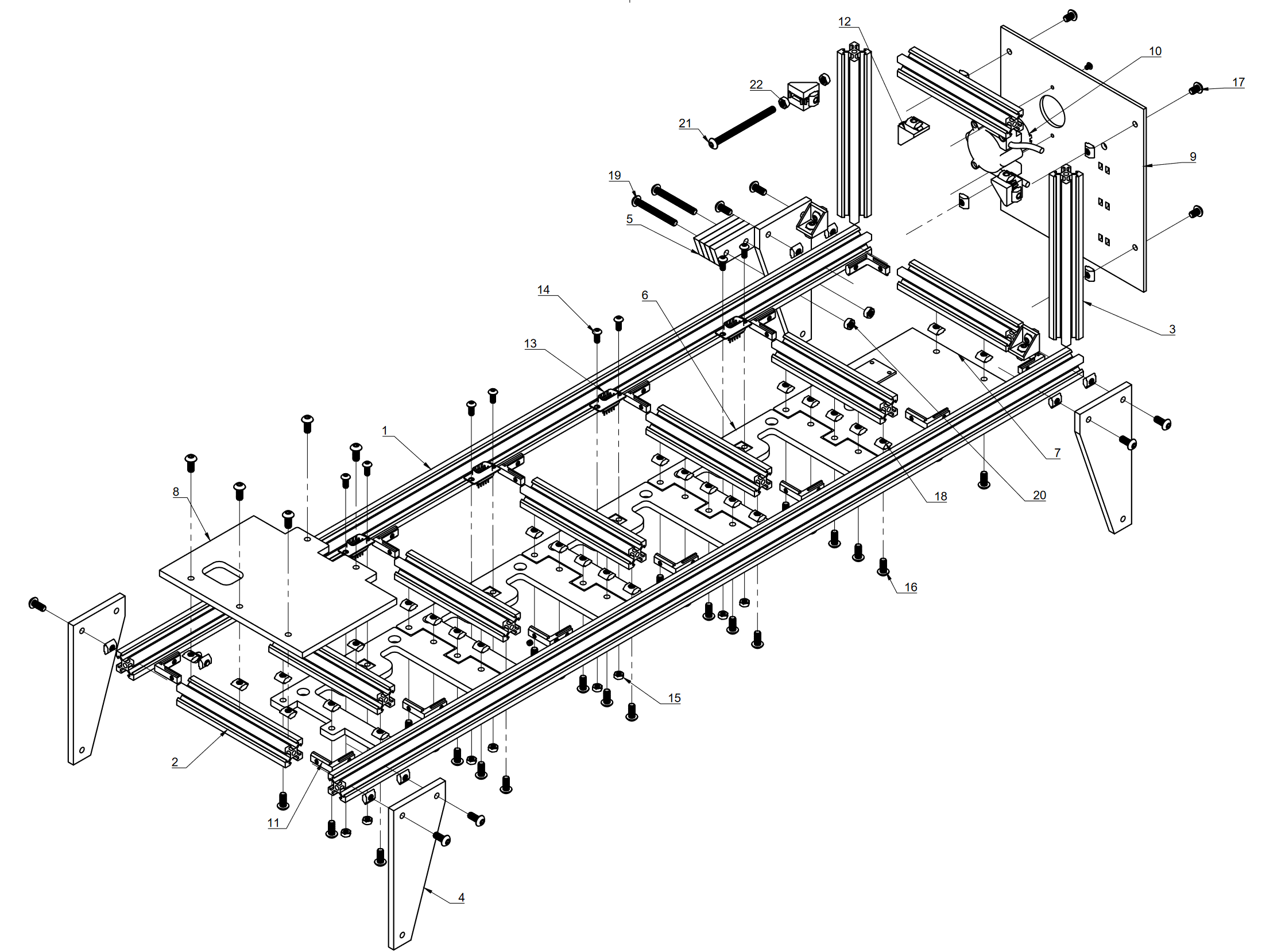
The final schematics called for an 18mm plywood construction (1-3), with a sheetmetal back (4), cut and bent to close off the back of the chamber. The front acrylic window (5) slots into the frame and isolates the module for atmospheric control. The plant pot itself (6,7) is made of a vacuum-formed body, paired with a injection-moulded retainer (7) for rigidity; it sits atop the plywood base. M4 bolts are the fixing of choice and make assembly (or disassembly for repair/recycling) possible with a single Allen key.
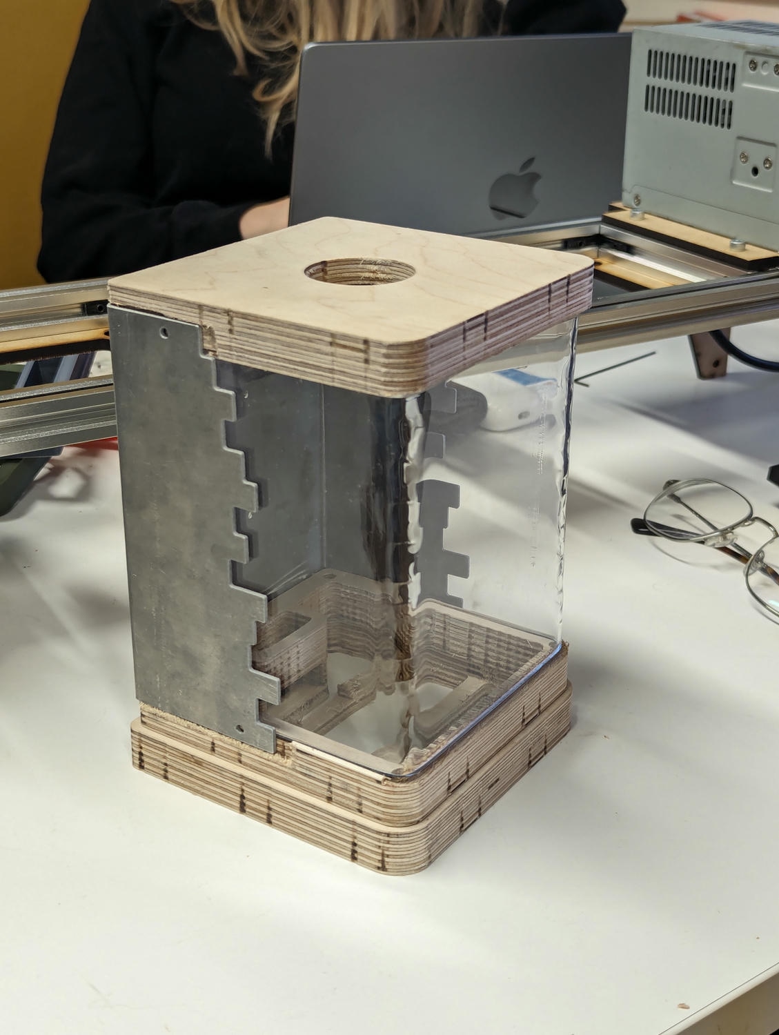
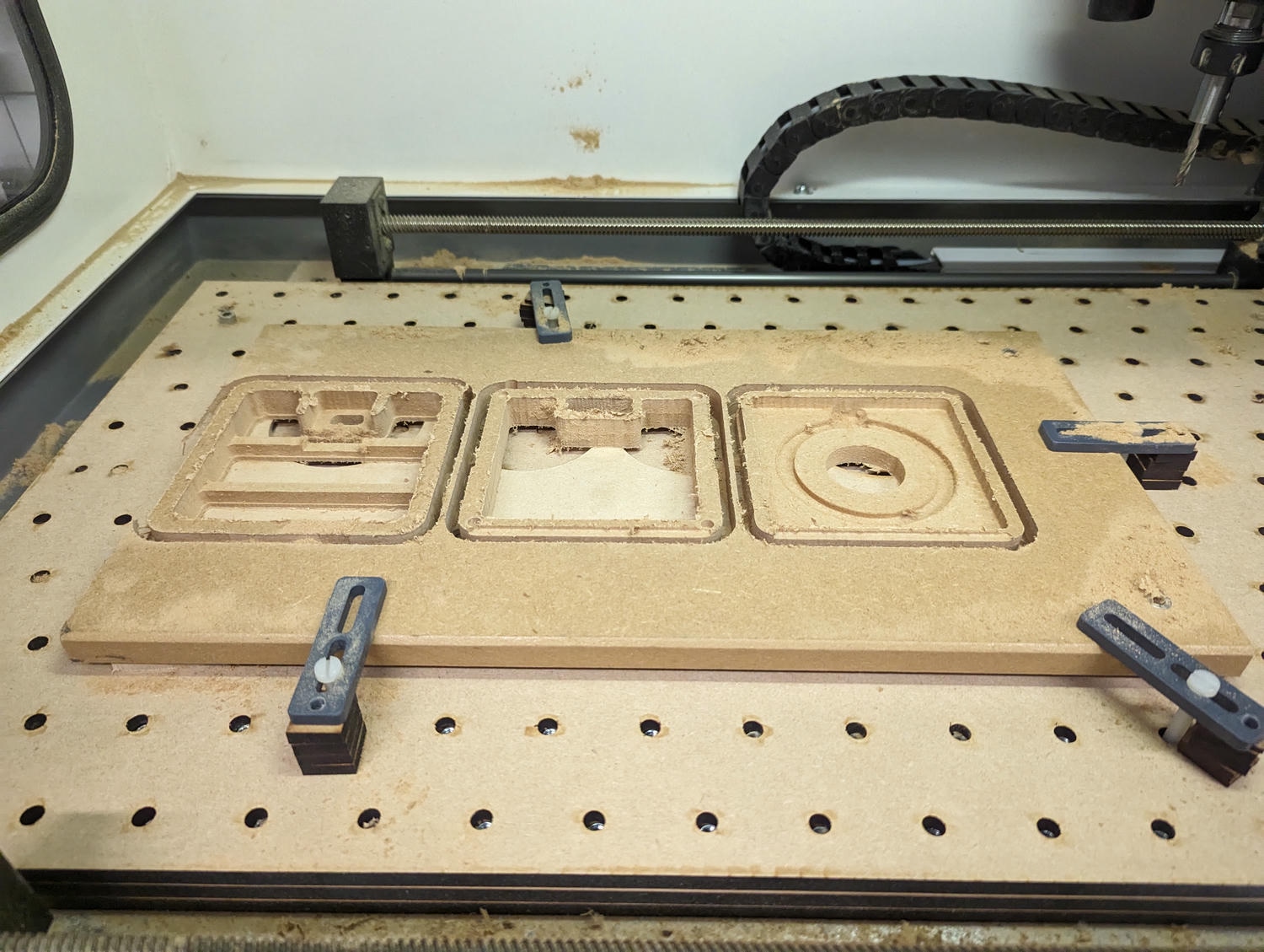
Prototype construction started at the CNC router and test cuts in MDF looked promising. As you can tell from my previous projects, I’m a big fan of good-quality birch ply, and the exposed edges looked great in render. Sadly, with a limited timeframe and tooling, we weren’t able to achieve the dimensional accuracy we had hoped for on the router, so were forced to revert to our backup: 3D printed parts.
The sheetmetal back was waterjet cut from 1.6mm aluminium. Given the freedom this afforded us in design, I couldn’t resist a bit of creative experimentation, and ended up with a blocky edge feature. It was then bent into shape using the Dyson Centre’s century-old centrifugal press.
Another manufacturing challenge was the removable front window. I was determined to have a curved single sheet construction to avoid the structural and aesthetic problems of an acrylic corner joint. Without a line bender, we resorted to using a hot-air gun over and a laser-cut jig: this worked well, with the final rippled corners diffracting the light beautifully. The only casualty was the Engineering Department’s hot-air gun, which packed it in halfway through the job!
Electronic design
With the functional requirements of the electronics decided, we drew up an interface diagram and assigned off the different sections. I was given the challenge of the module (“GrowPot”) circuitry and went in keen to use some of my past PCB design experience. Fortunately, this was a sensible application, as we needed three identical circuits for our prototype.
One major challenge was communication between the modules and the controller. The design called for a mechanical connection to a stationary power rail, but to avoid the potential time-sink of diagnosing a physical data link, an MQTT wireless bus was employed. Each module contains a Pico W which communicates directly with a host server on the carriage.
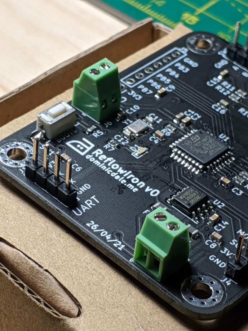
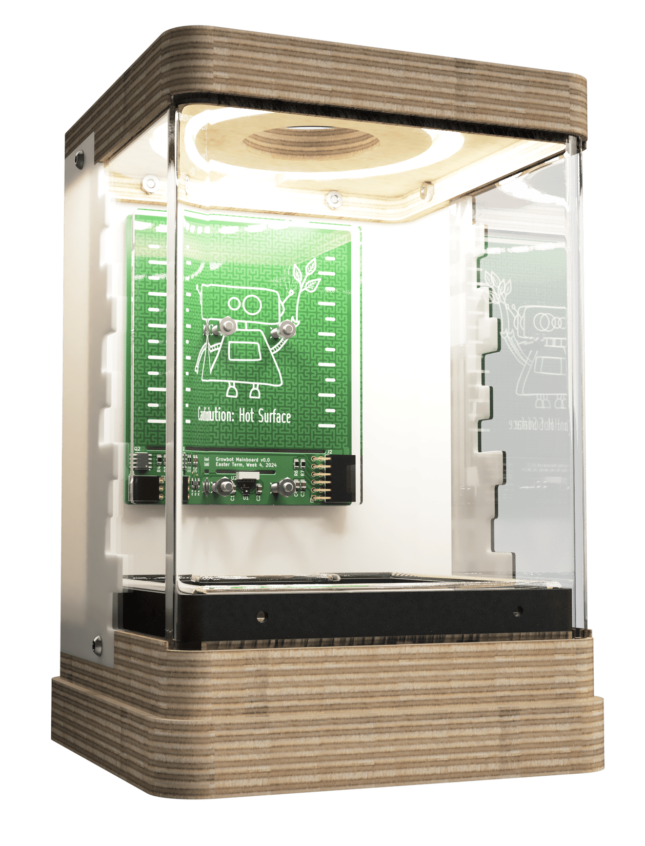
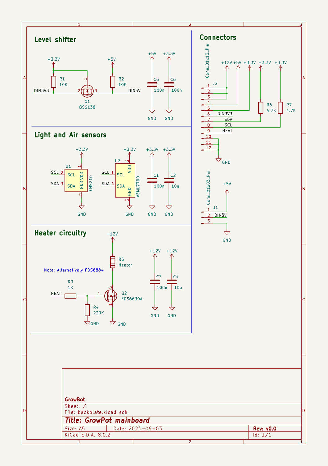
The module PCBs have to handle both measurement and control of the pod’s environment. Light and air sensors are located at the bottom of the board and thermally isolated with slots. An external LED ring provides lighting control, with an on-board level shifter ensuring the 3V3 logic of the Pico can properly drive it.
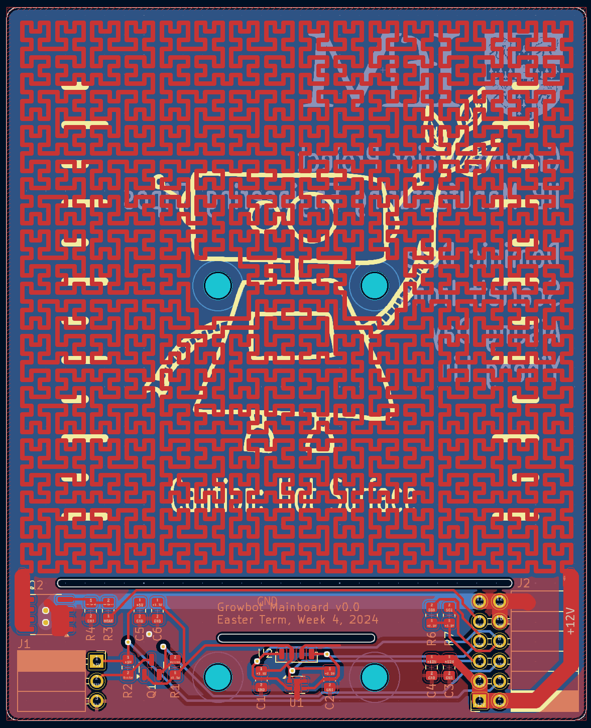
The most interesting part of this design is the integrated heater. By specifying a trace’s length, width and thickness, we can calculate its resistance:
\begin{aligned}&
R=\rho \cdot \frac{L}{TW}\cdot \left[ 1+\alpha\cdot(t-25)\right] \\
&\rho - \text{resistivity}\\
&\alpha - \text{temp. coeff}\\
&t- \text{temp. in celcius}
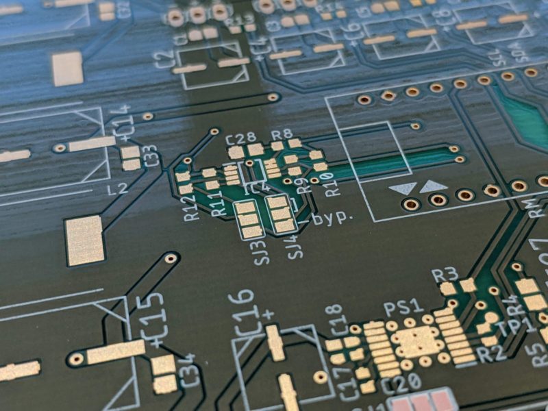
\end{aligned}The design resistance is around 3Ω, meaning that, with a supply voltage of 12V, the heater draws 36W. The trace itself follows a ‘Hilbert curve’ fractal which was generated with a script to the 6th iteration – the end result is a trace roughly 4.5m long. After generating, the vector graphic was imported as a custom footprint into KiCAD and modified to allow for two mounting holes through the middle. The heater itself is driven by a power MOSFET. Some final decorative silkscreen completed the design, and I was really happy with the completed look on the manufactured boards.
With the help of hot air and a steady hand, assembly went smoothly (even for the ENS21 – with a 2mm concealed pad footprint!). Because the design turnover on the board was so fast, I expected to find few issues on in testing. To my great satisfaction, no such issues emerged.
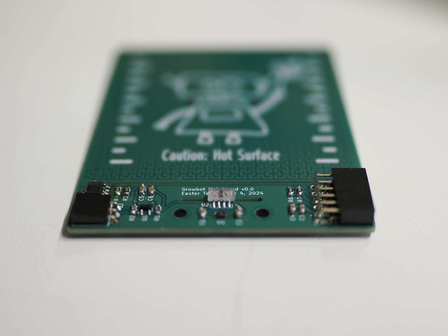
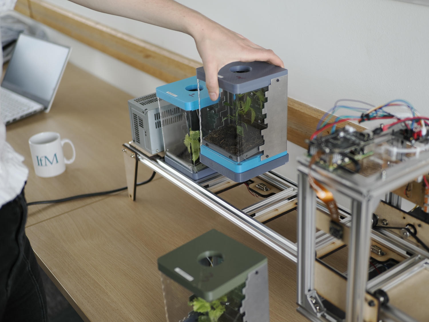
The modules are hot-swappable, with a DB-9 plug acting as both an electrical connection and mechanical constraint.
Frame
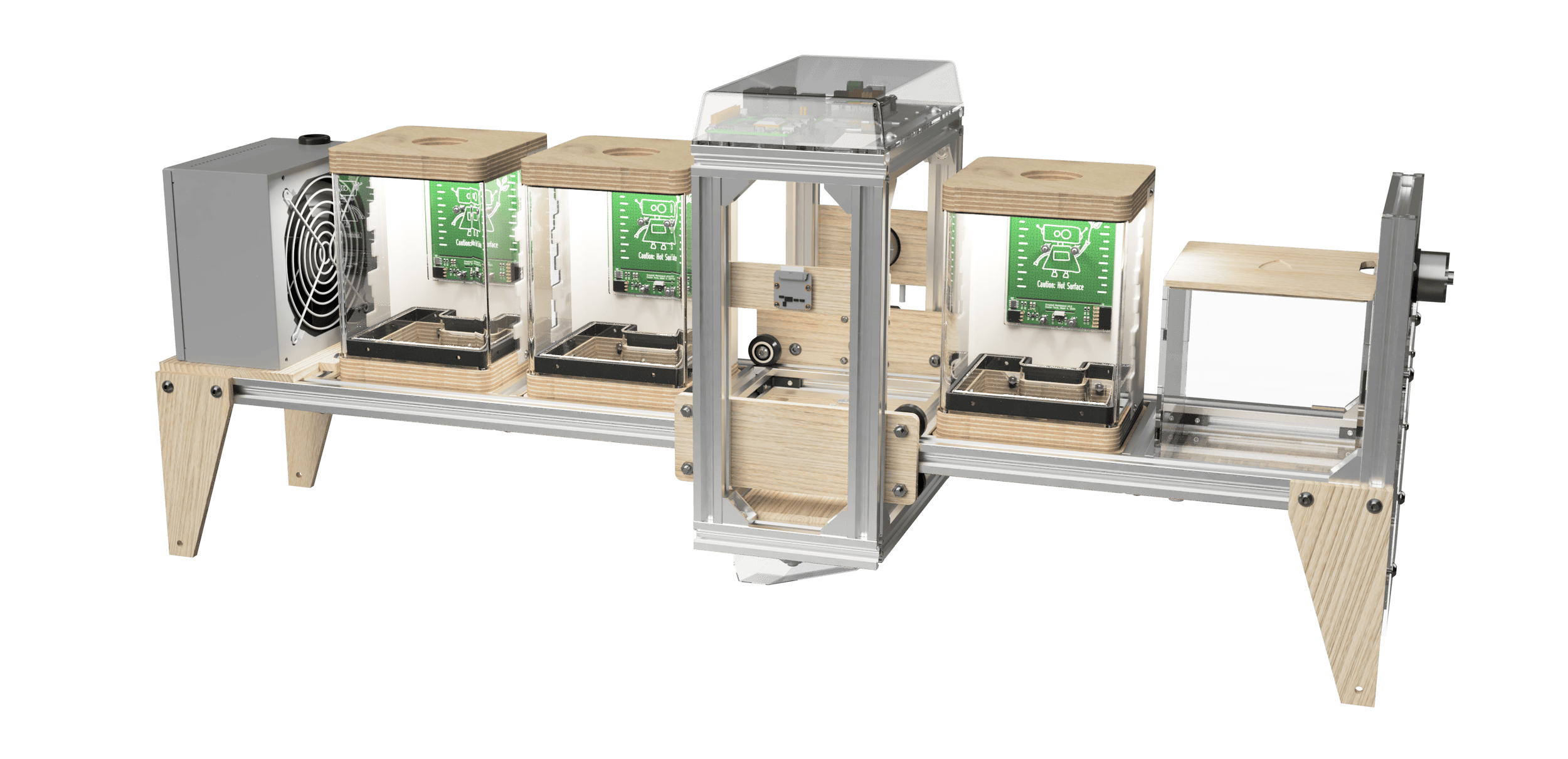
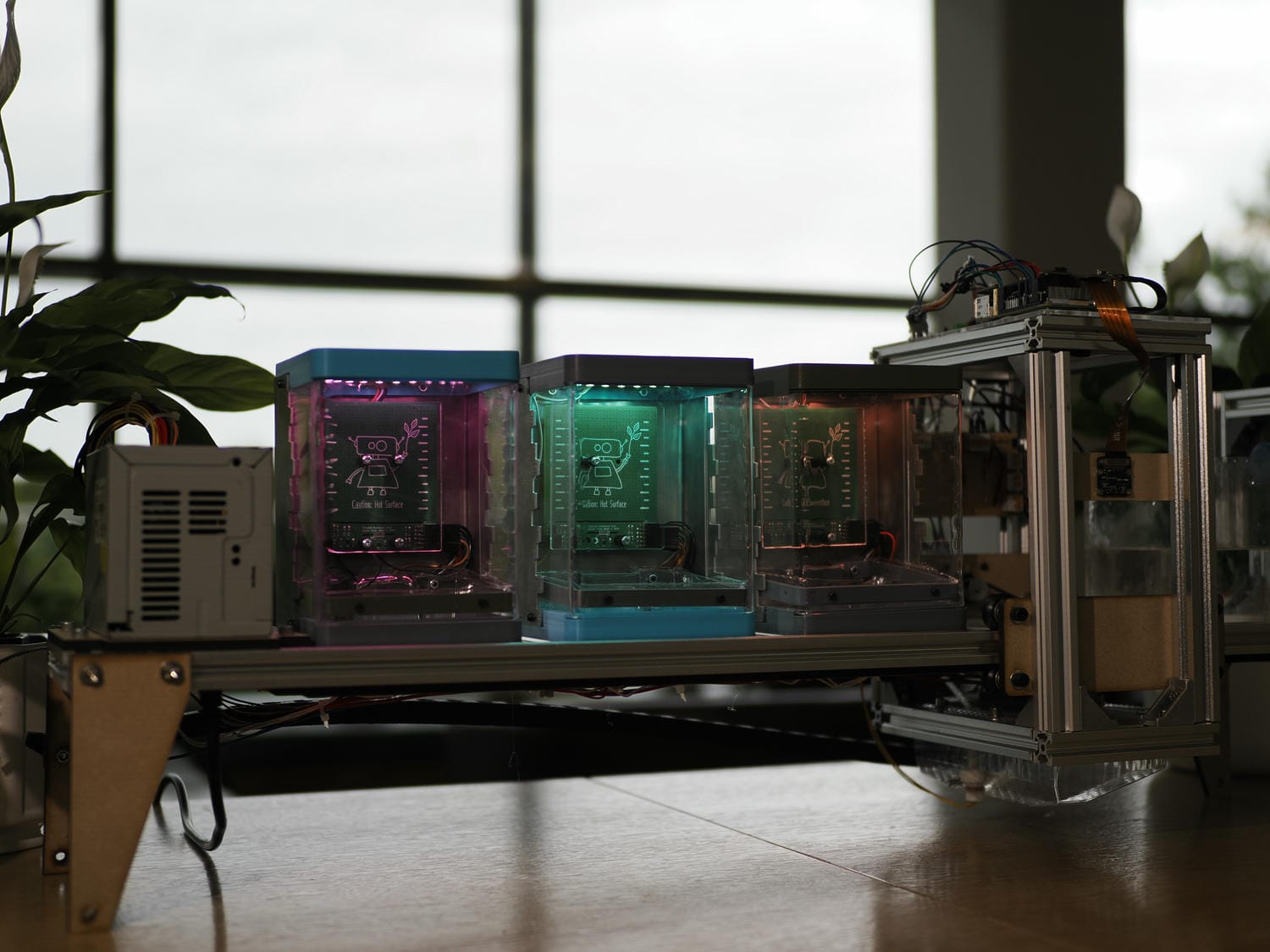
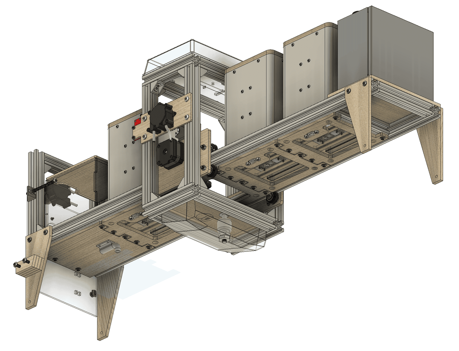
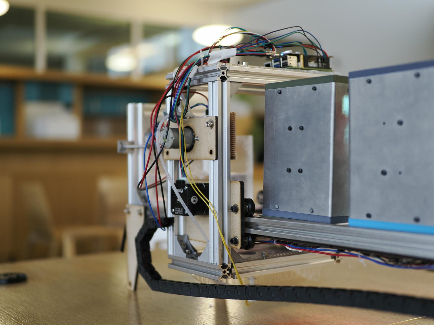
Using 2020 aluminium v-slot for our frame meant we didn’t need to worry about separate linear motion and structural components. The frame is designed to be expandable, making 20 or 30-module GrowBots feasible for a full family of GrowPots – these modules would all be serviceable by a single carriage. All aboard!
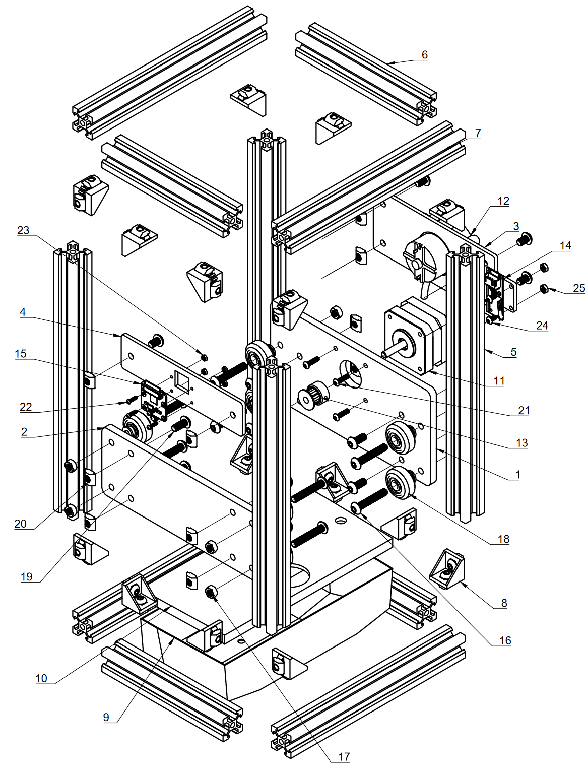
The carriage was similarly constructed and designed to move along the frame with internal v-wheels. Watering and photo-taking hardware (for plant growth monitoring) was mounted for multi-module use.
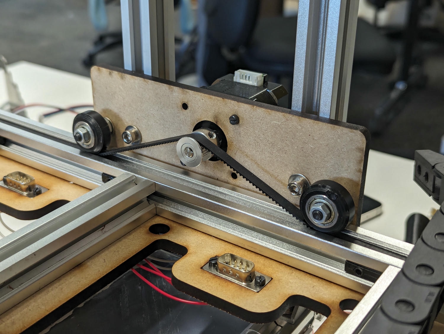
The drive mechanism used is a ‘belt and pinion’; a single carriage-mounted motor pulls the carriage along the frame. To keep the belt out of the way, we ran it down the frame extrusion, and used the existing v-wheels as idlers. The wheel spacing was wide for stable movement, but this had the consequence of a shallow belt contact angle on the pulley; fortunately there was no slippage.
Aside from the v-slot, most structural parts were laser-cut from 5mm MDF and fixed with M5 screws. The watering system consists of a primary tank in the base of the carriage (vacuum-formed PETG), and a secondary stationary tank for automatic refills. Float switches in each tank detect low-water conditions and inform a machine response.
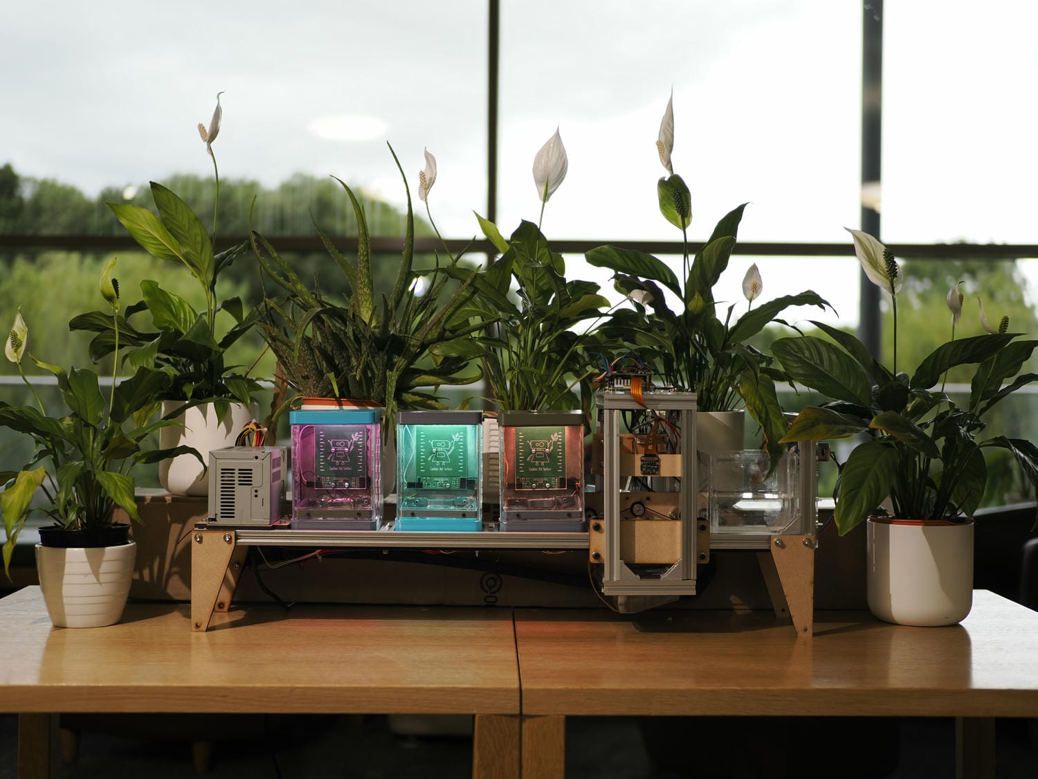
Finished product
There were a few more things to think about, including cable management and the pump circuitry, but the majority of the final workload was in software. The web interface, hosted on the Raspberry Pi controller, enables remote configuration and interaction with each module. It also allows students to view historic environmental conditions and how the plants have developed over time.
We finished the project within the deadline, suggesting at least some success in project scoping and time management. All that was left to do was pitch the idea to the cohort.
Reproduced on A0 paper, our Fusion renders looked stellar, and paired with convincing pedagogical arguments about the interactive value of the GrowBot, the event passed smoothly. We had a fully-functional prototype, which we were all happy with, and were delighted to be awarded the MET IIA Major Project prize for best overall product. Hurrah!
Working in teams and to deadlines isn’t something I’m used to in my personal engineering projects (many of which remain unfinished after 5 years!), but it is brilliant to see what can be achieved with effective organisation, delegation and motivation.